Wipers
Posted: Tue Sep 14, 2010 1:02 pm
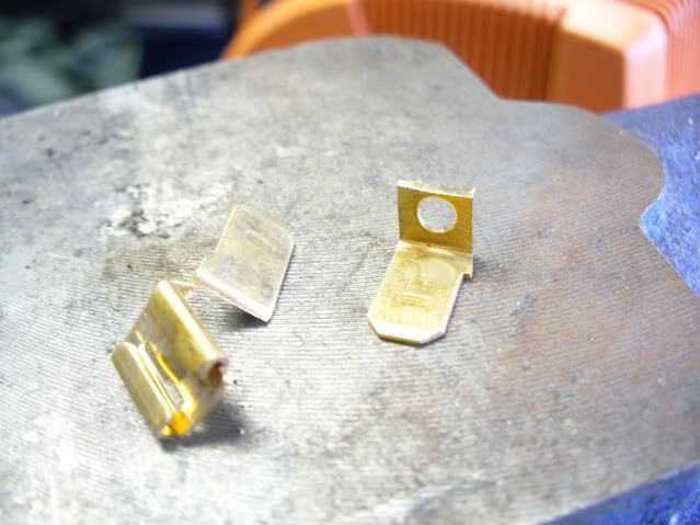
sdwalter wrote:So I found this thread while searching for how to rebuild a wiper motor. Mine stopped working, which of course you always discover when it is raining. It turns out my problem was a broken rivet on one of the electrical terminals. You can see it here:
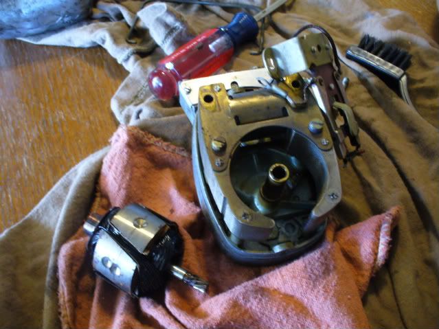
While I was at it, I decided to try to follow kubelmann's instructions and completely disassemble the motor and clean everything up. I took some pictures along the way to help me remember how everything goes back together. You can find a bunch of them in the gallery, but I linked to some here along with Kubelmann's instructions.
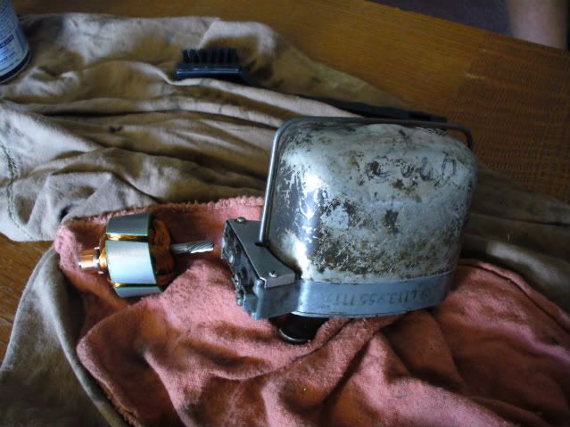
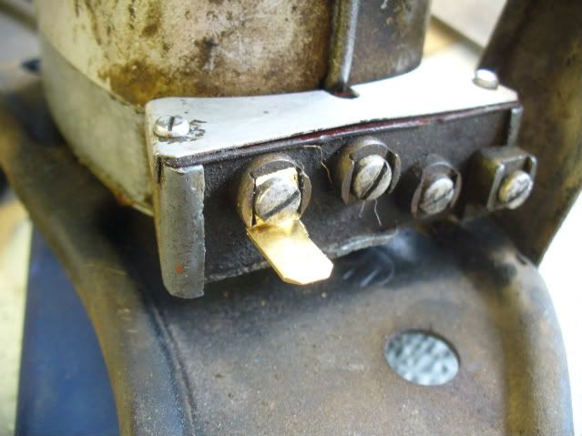
Here is a picture of mine at this stage. Notice mine is missing the copper contact that was connected with the broken rivet.kubelmann wrote:The following post is to be used at your own risk and by those that have some experience with repairing delicate automotive electrical devises. I have decided to post this as an attempt to help. It comes from the RoMTOC Thing Data CD.
glutamodo wrote:Generic "voltadrop" resistors aren't the greatest, they aren't always an ideal resistance.cncwhiz wrote: I have heard a lot of bad things about dropping resistors? ?
I've had my 1962 6V single speed motor hooked up with two dropping resistors on a two speed wiper switch for years now. One of the resistors I use is a high-wattage adjustible type, which is nice for winter to get them to run faster when it's cold out.
http://www.thesamba.com/vw/forum/album_ ... _id=398182
DL West-Wiperguy wrote:Hi I'm the wiper guy. I can help you get the correct unit for your car in 12 volt. DL West [email protected] (503)434-3530
The Thing wiper motor assembly is a standard DC motor
with some gears and electrical controls built in. The electrical controls are used to return the wiper arms to the parked position
when the wiper switch is turned to the 'OFF' position. During the following, be sure to keep track of all the various pieces and
screws. Clean everything as it is taken out.
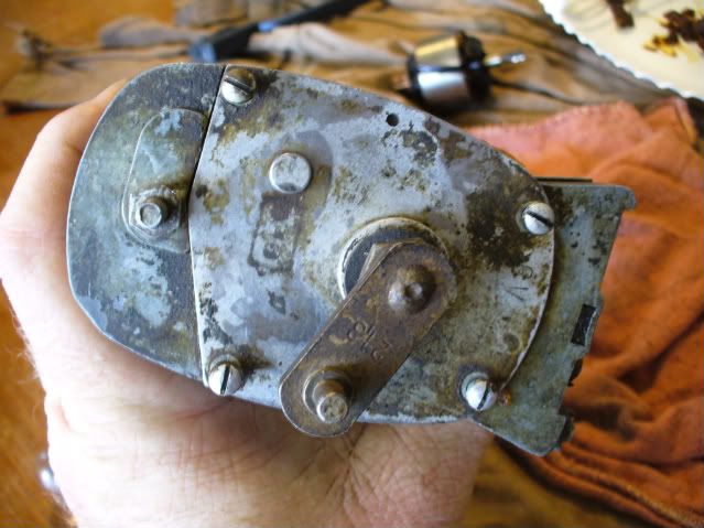
¨ The wiper motor is held to the windshield by a single nut on the wiper shaft. After removing the wiper arm, the large nut,
washer, and rubber washer should come off and the wiper motor can be removed.
CAUTION!!
There are wires connected to the left side of the motor.
+-+-ONE OF THE WIRES IS HOT WHENEVER THE KEY IS ON -+-+
For safety, disconnect the battery before working on the wiper motor.
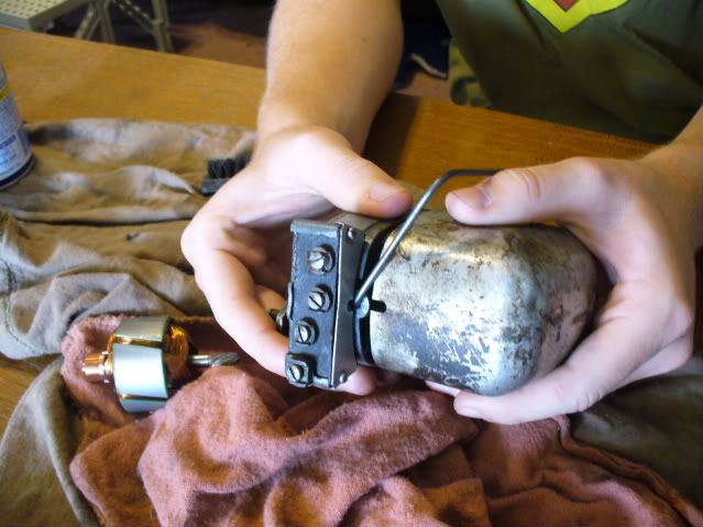
¨ There are two small screws that hold a U shaped bracket. The bracket is used to hold the wire harness to the side of the motor.
The harness has a loop built in to provide room for the harness to flex when the windshield is lowered.
¨ Get a paper, pencil, and note the color of the wire on each lead on the wiper. There will be a brown wire. Brown is always
used for wires that goes to ground on VW's. The other wires are black, green, black with a white stripe, and black with a green
stripe. These are the power leads.
¨ There is a bail, or wire clip that holds on the cover to the motor, like the ones that hold on the valve covers. Slide it to one side
and remove the cover. Remove the bail and the plastic gasket that seals the cover to the housing.
¨ On the side of the motor where the wires were connected, there is a plate held in place with two screws. Remove the screws,
plate and insulating paper. Gently slide the plastic bracket that holds the connectors in place, straight up. It should be
connected to the rest of the motor with two wires which are connected to the brushes.
¨ On the back of the plastic assembly, there are copper spring contacts. They are moved by a pin that sticks out from the side of
the motor. Remove the pin by pulling it out.
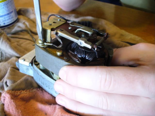
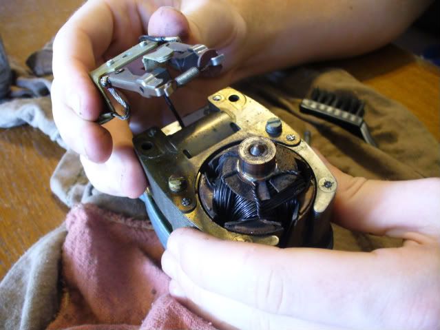
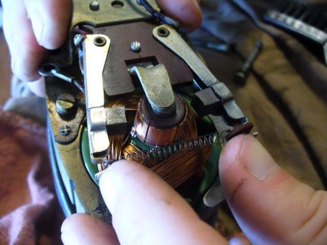
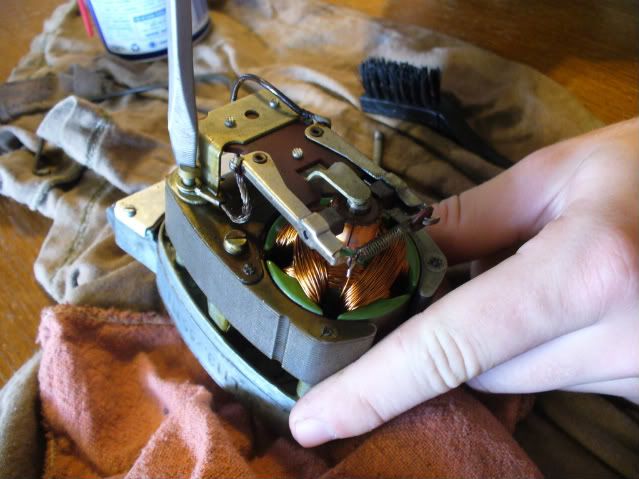
A picture with the brush circuit board and contacts removed.kubelmann wrote: ¨ Inside the motor, you will see the brushes that provide connections to the rotor. That part is wrapped with a lot
of copper wire and spins inside the frame. Two of the brushes should have a wire that goes to the plastic terminal strip removed
previously. The third brush has a braided wire that is connected to a screw on the frame of the motor.
¨ The bracket that holds the three brushes and holds in the top of the rotor is held in place by two screws. Remove the screws and
gently lift off the bracket. Try to keep the brushes from coming out of their holders.
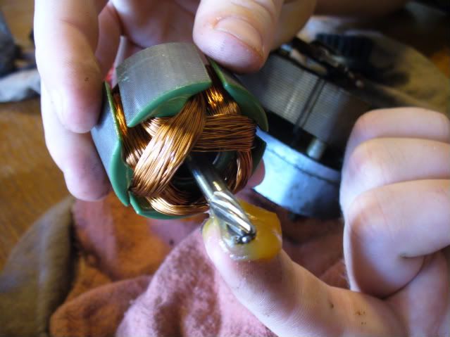
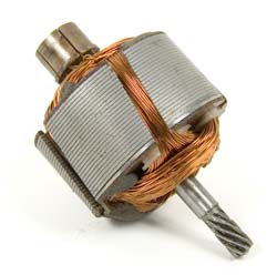
kubelmann wrote: ¨ Now, the rotor can be lifted out of the frame of the motor. Be careful not to nick the copper wires when prying it out. It will be
'stuck' because there is a strong magnet inside the frame.
kubelmann wrote: ¨ Remove the other two screws on the top of the magnetic frame and remove it from the motor housing.
kubelmann wrote: ¨ Now turn the assembly over so that the main wiper shaft is pointing up. There are four screws holding the cover in place.
Remove them and lift the plate up off the wiper shaft.
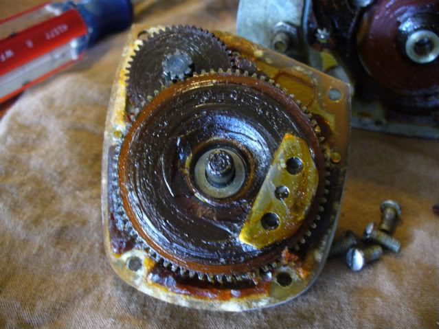
¨ This reveals the first gear assembly. These very large gears are used to provide the oscillating movement to the main shaft.
Make notes regarding the position of the gears for use during assembly.
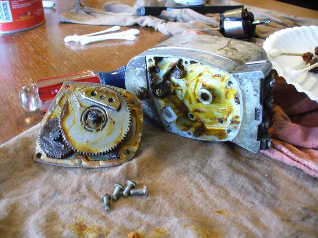
There are actually 4 screws that hold the upper gear case to the motor frame. You will only see three in the picture because I took one out before I remembered to take the picture. The one in the upper left corner has already been removed.kubelmann wrote: ¨ There is a retaining clip on one of the shafts. Remove it and lift the gear assembly out. There will probably be a lot of old grease
that has gotten hard and needs to be cleaned out.
¨ After the upper gear assembly is removed, and the grease cleaned out, remove the three screws holding the upper gear case to the motor
frame. The case and the cover for the lower gear case will now come off and the speed reduction gears will come off with it.
kubelmann wrote: ¨ Before the cover is completely removed, note the position of the gears!!!!!!!!! Two gears will come off. One large,
and one small. These also, will be caked with old grease, which must be cleaned.
¨ On the larger gear, there is a plastic cam with a flat spot on one side. This cam is used to push the pin out the side of the motor,
that is used to close the contacts, that is used to keep the motor turning until the wiper arms are back to the home position when
the switch is turned off.
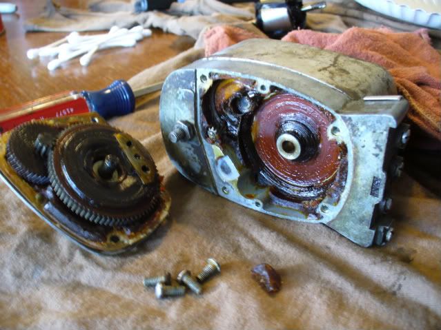
Here is the housing with the grease cleaned out.
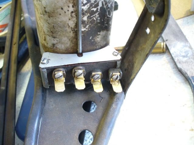
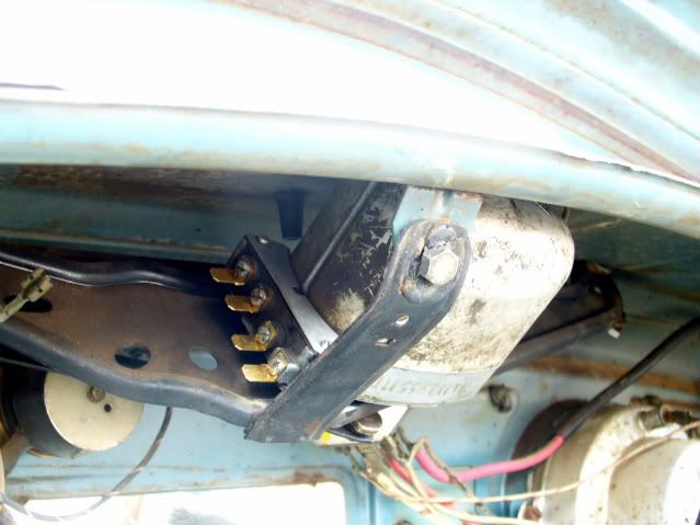
And finally, a picture of the motor reassembled. Notice that I cut the wires where they attached to the brush housings because they were really frayed and soldered them back to on. I should have taken a picture before I replaced the white cover on the contacts. I replaced the broken rivet with a #8 brass machine bolt and nut.kubelmann wrote: The motor is now completely disassembled. Assemble in the reverse manner. During assembly, watch the following.
¨ Replace the grease on the upper and lower gears with wheel bearing grease.
¨ The two speed reduction gears must be replaced with the smaller one placed between the larger one and the cover plate. It is easy when there is a lot of grease holding all the parts together.
¨ To get the proper position on the upper gears, insert the commutator shaft through the housing the way it would be but without the magnet frame installed. There are gear teeth on the end of the rotor shaft that engage with the speed reduction gears. You can spin the rotor, which will move the speed reduction gears, and will move the upper gears. When the upper gears are properly aligned, they will move through the complete cycle without binding or hitting the side of the case.
¨ The main shaft may have become corroded which will cause it to bind in the shaft on the housing cover. Clean it and grease as necessary. I use grease that is used on bicycle wheel bearings and is considered somewhat water resistant.
¨ Remove the rotor, and reinstall the magnetic bracket. Before reinstalling the rotor, use 1000 or 1500 grit emery paper to wipe the slotted copper contacts on the top of the unit. Shine them up. After doing that, use an xacto knife and clean out any copper dust or any other dirt that may be in the slots between the copper contacts.
¨ If you have an ohmmeter, use it to verify continuity between the copper segments on the opposite side of the shaft. If there is no continuity, the windings may be bad and the rotor may have to be rewound.
¨ Check the brushes. They should slide easily inside their holders. Hopefully, they did not come out of the holders when the bracket was removed from the motor. If they did, the easiest way to replace them is to pry open the back of each brush holder, remove the spring, and slide the brush into the holder. Replace the bracket over the end of the rotor, and screw it down. Then, slide the springs back into the holders, and bend
the tabs back over the ends to hold everything in place. Try to bend the brush housing tab as little as possible because if it breaks off, it may be difficult to salvage the job.
¨ Check the wires that go from the brush holders to the plastic bracket that mounts on the end of the housing. If they are frayed or the insulation is cracked, get out the soldering iron and replace them.
¨ Be sure to replace the pin in the side of the motor housing before sliding in the plastic bracket.
¨ Do not connect the wiper arms to the wiper motor shaft until you have connected the wires to the motor and run the motor through a complete cycle. Let the motor stop by itself when the switch is turned off. Failure to do this may result in the wiper arms scratching the paint, as they may not be properly aligned.
Wiper motor repair
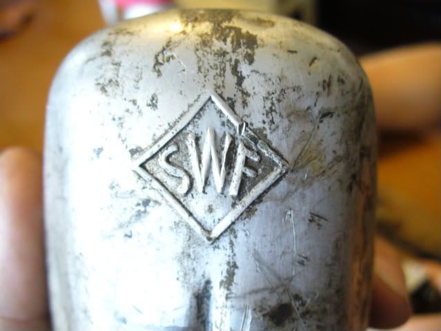
To "rebuild" a Type 181 wiper motor it is necessary to replace the armature, and possibly the brush assembly. These parts can be salvaged from a type 1, two speed, 12-volt wiper motor manufactured by SWF. This type of motor has a bail to retain the cover and is stamped SWF directly under the bail, it will look very similar to a Thing motor. Unfortunately, I do not know what years this type of motor was used in Bugs. After the correct wiper motor is acquired, it is a simple process to remove the two screws retaining the brush holder, remove the old armature, and replace with the "new" armature. Replacement of the brush assembly can be accomplished by unsoldering the brown and black wires from the type 1 terminal card, and resoldering to the type 181 terminal card in the same locations. Once the motor is reassembled clearances "a" and "b" need to be set according to the VW repair manual section 8.0. Additionally, it is very important to determine what caused the motor to fail in the first place; the troubleshooting section of the VW manual is a good place to start. I also suggest reading the precaution section 8.2.
Well, that's my story. Hope it is useful.
Scott