Page 1 of 2
Need 1974 Standard Fuse Panel Wiring Help
Posted: Thu Mar 19, 2009 9:32 am
by david58
Posted: Thu Mar 19, 2009 11:36 am
by david58
Livens wrote:Has anyone noticed that the Fuse diagram for a 1972SB that is in the Technical section is wrong?
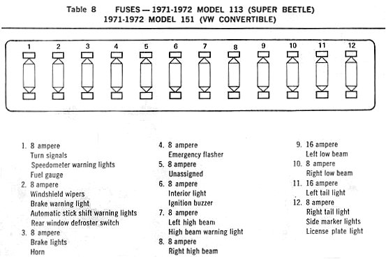
It shows the #3 fuse being for the brake lights, but its not, its for the left headlight. Several other mistakes on it too. If you look at the wiring diagram itself, you can follow the wires and see that it is wrong. Also while tracking down a brake light problem I found out first hand.
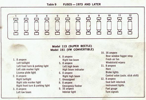
But this has me wondering if the fuse sizes are wrong too? When i got my beetle the fuse box looked like a rainbow, every size fuse was used, and none of them matched what whats on the fuse diagram. Well it still looks like that, but i want to straighten it out. I bought 10 8amp and 5 16amp fuses to replace eveything.
Look at the
#8 fuse: 8amp; Right high Beam. The look at the
#9 fuse: 16amp; Left low Beam.
The low beams get a smaller fuse than the high beams?
Also is there anyway to tell what size is needed from the wiring diagram?
Posted: Thu Mar 19, 2009 12:49 pm
by david58
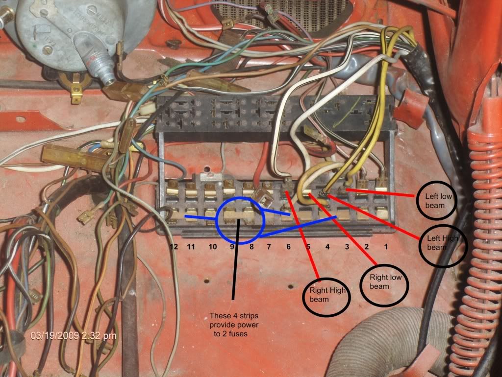
Looking at the fuse panel and wiring diagrams online everything in the diagrams seems backwards when looking at the wiring on the fuse panel. So I have re-numbered the panel in the pic to make it easier to understand. Does anyone have a pic of the fuse panel in their car that is stock? I think I have this wired up right so far but before I continue I want to make sure it is right.
Posted: Thu Mar 19, 2009 6:46 pm
by Speedy Jim
You're on the right track.
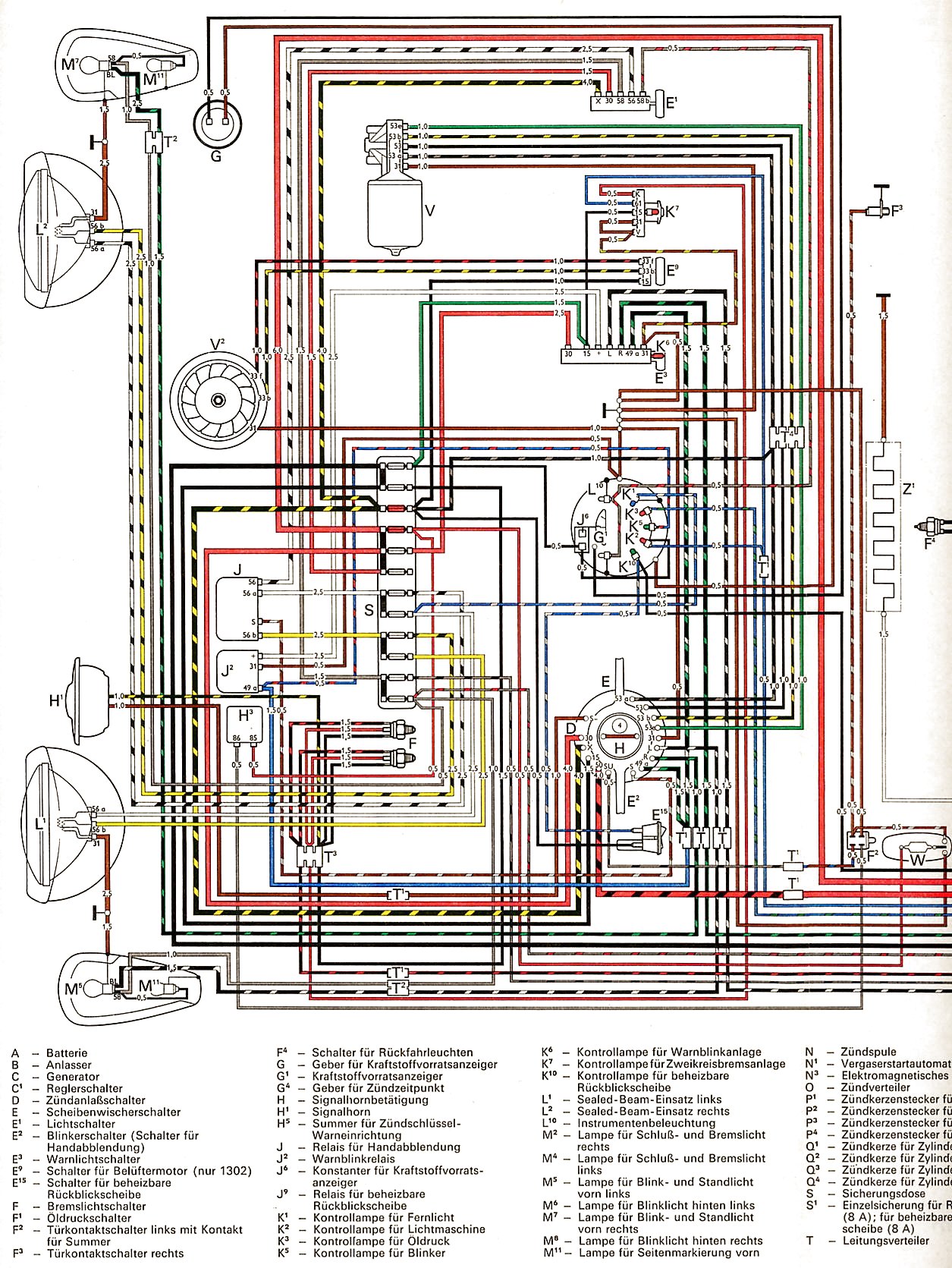
Download this diagram for 1972:
http://www.vintagebus.com/wiring/1300_a ... 1971-1.jpg
It is essentially correct regarding all the fuse block wiring and numbering for your car.
See how far you can get and post back where any problems exist.
Jim
Posted: Thu Mar 19, 2009 7:07 pm
by david58
Thanks Speddy Jim it is alway a blessing when you post.

Posted: Fri Mar 20, 2009 7:49 am
by david58
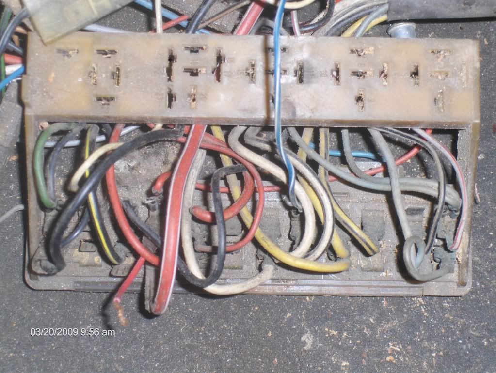
While looking thru some boxes for the bulb holders for the speedo lights I found a fuse panel with all the wires still connected.

Posted: Fri Mar 20, 2009 7:58 am
by Speedy Jim
Wow! That's a good find.
Should be helpful for you.
Jim
Posted: Thu Mar 26, 2009 7:52 am
by david58
Speedy Jim wrote:Wow! That's a good find.
Should be helpful for you.
Jim
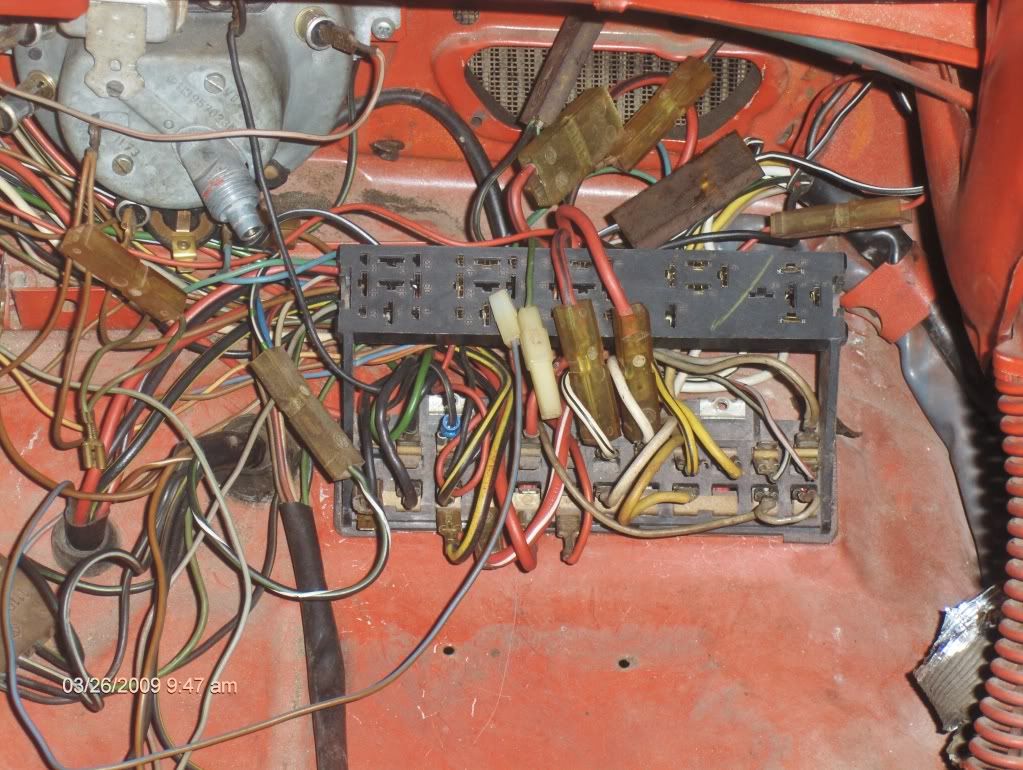
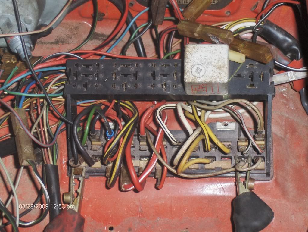
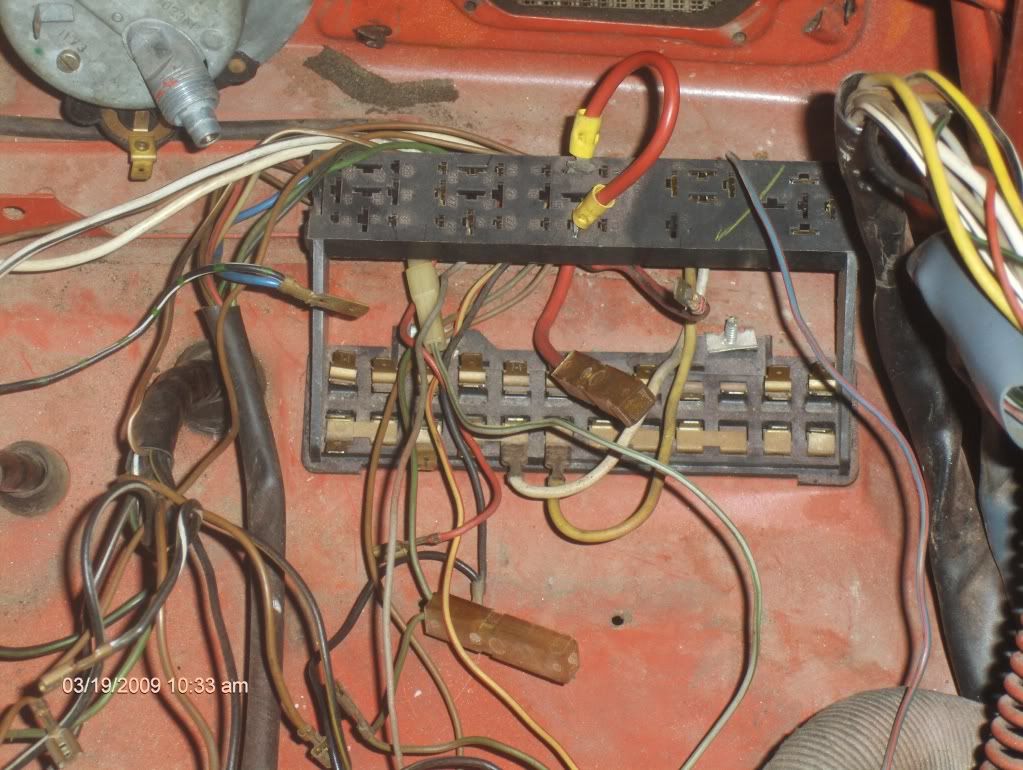
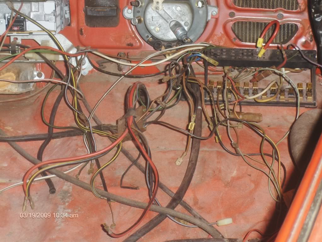
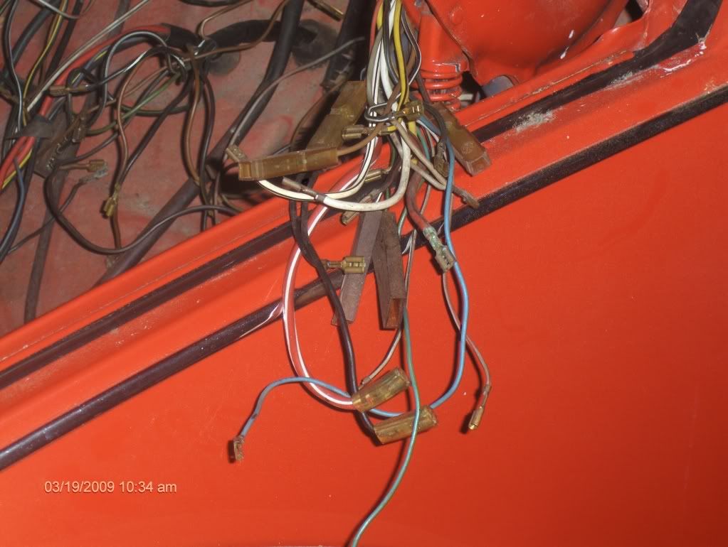
It was helpful but the fuse panel wiring wasn't exactally the same. In the pics below there are three wires coming out of the relay portion of the fuse panel.
1. the little green one.
2. A big red one with a black stripe on it just like the one from the ignition switch that energizes the starter. The starter works with the key.
3. And the big red one next to it.
Are these wires just extra or am I missing something? I don't see them in the diagram.
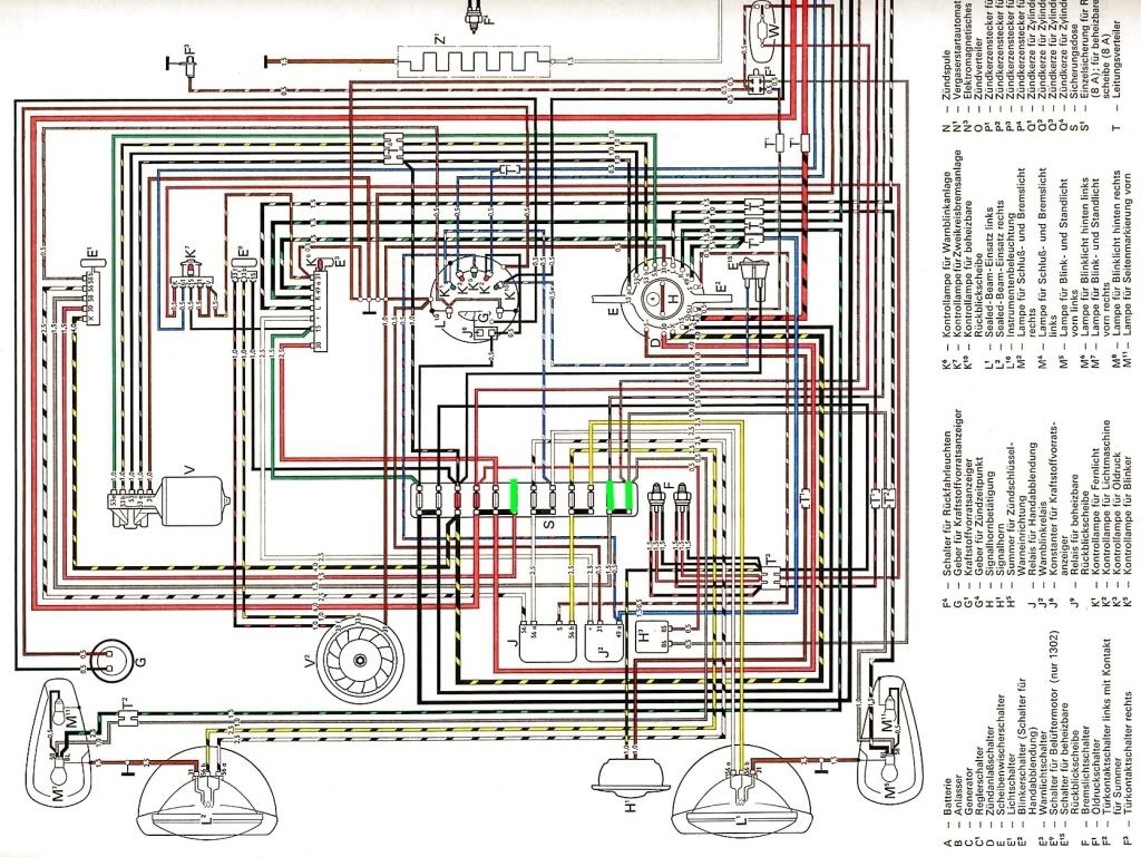
Below is the diagram Speedy Jim told me to download. It was a big help.
But the three fuses I highlighted in green do not have the buss bar in them like in the diagram. So I am wondering if I have the correct fuse panel?
Posted: Thu Mar 26, 2009 8:01 am
by Speedy Jim
Your box is only slightly different. Notice that there is a Gry jumper wire between the 2 fuses on the right; that takes the place of the brass bar.
The extra wires, such as the Red/Blk were probably for the seat belt interlock found on '74 models.
My simplified sketch of the starter section of the circuit:
Posted: Thu Mar 26, 2009 8:08 am
by david58
What about fuse 7 it isn't jumpered? In the diagram it has a buss bar on fuses 7, 8, and 9.
Posted: Sat Mar 28, 2009 10:23 am
by david58
david58 wrote:What about fuse 7 it isn't jumpered? In the diagram it has a buss bar on fuses 7, 8, and 9.
Never mind about fuse # 7 it is a spare.
I need to figure out why I don't have power with the key on on fuses 1 and 2. I jumpered power from fuse 12 to 1 and 2 and have tail lights as you can see in the pic below. I know I am missing some relays I only have the one in the pic.
J is the dimmer relay
J2 is the emergency flasher relay
What is H3? I can't find any info..........

Anyone have part #'s?
http://i147.photobucket.com/albums/r301 ... ng-key.gif
Posted: Sat Mar 28, 2009 2:49 pm
by Speedy Jim
H3 is the door ajar buzzer. Disregard it.
The 2 fuses with Gry wires aren't supposed to have power with the key On.
They only get power when the Headlight switch is pulled out; they feed both parking and tail lights.
The 2 fuses with Blk wires are live when the key is On.
Jim
Posted: Sat Mar 28, 2009 2:53 pm
by david58
Speedy Jim wrote:H3 is the door ajar buzzer. Disregard it.
The 2 fuses with Gry wires aren't supposed to have power with the key On.
They only get power when the Headlight switch is pulled out; they feed both parking and tail lights.
The 2 fuses with Blk wires are live when the key is On.
Jim
I should have been clear I am not getting power on fuses 1and 2 with the key on and the headlights on.
Posted: Sat Mar 28, 2009 4:25 pm
by Speedy Jim
Ah.
Your '74 has
two separate power feeds to the Headlight switch, like this:

The Red wire on #30 supplies the park/tail lights. See where that is connected and if it's live.
Jim
Posted: Sun Mar 29, 2009 6:01 am
by david58
Thanks Speedy that clears up some confusion. My car is at the shop but if I remember correctly that is all hooked up that is were fuse # 7 is missing the buss bar. Easy check I will put power to the red wire going to # 30 and see if it powers up fuses 1 and 2. I also found a better key legend to the diagram in English.
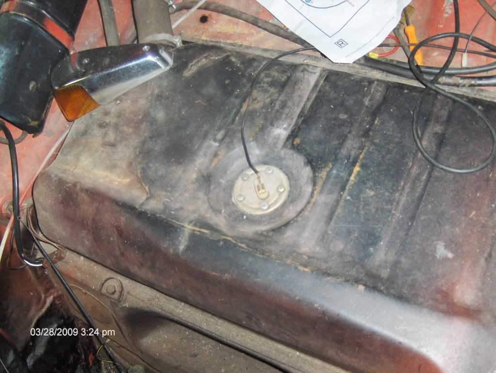
The next thing that is different in the diagram is the fuel sender on the car it only has 1 wire?
The diagram shows 2 wires.
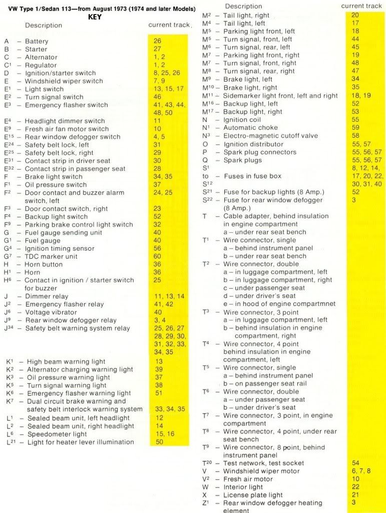
Note
H3 is the door ajar buzzer


