That roll cage B-pillar does not HAVE TO be vertical. It CAN lean inward some. But it SHOULD foot outboard against the body mount lip on the pan. Let it be against the top edge of the body if you want. Maybe even put a tab on the side of the tube to the top lip on the body.
AGAIN, you do NOT need to attach the cage base to the lower level of the floor pan. The base plate need not extend so far inboard. But the vertical part SHOULD extend up to the top edge of the body lift tube with bolts above and below the center weld line of the rectangular tube.
See my email for more, Lee.
Ol'fogasaurus black buggy
-
dustymojave
- Posts: 2312
- Joined: Mon Dec 01, 2008 9:08 pm
Re: Ol'fogasaurus black buggy
Richard
Lake LA, Mojave Desert, SoCal
Speed Kills! but then...So does OLD AGE!!
Tech Inspection: SCCA / SCORE / HDRA / ARVRA / A.R.T.S. OffRoad Race Tech - MDR, MORE, Glen Helen BajaCup
Retired Fabricator
'58 Baja with 955K Miles and counting
Lake LA, Mojave Desert, SoCal
Speed Kills! but then...So does OLD AGE!!
Tech Inspection: SCCA / SCORE / HDRA / ARVRA / A.R.T.S. OffRoad Race Tech - MDR, MORE, Glen Helen BajaCup
Retired Fabricator
'58 Baja with 955K Miles and counting
-
Ol'fogasaurus
- Posts: 17758
- Joined: Mon Nov 13, 2006 10:17 pm
Re: Ol'fogasaurus black buggy
Not sure if I am going to be able to post photos as it is looking like Photo Elements are playing around like Photobucket did and is doing so this is a test!
My computer is also whacked out also, so it isn't working correctly either.
This is more or less what I am planning on doing as it seems like I am not being able to converse well.
The 3" vertical leg is pretty much covering the body lift (there is a small hang up which is obvious) but it is close to what I am planning on doing. The angle has a slight bend to it still, but it isn't the final piece... just a mockup piece.
The spacers on the floor add up to 2" high. The gap between the upper part of the pan and the angle bracket is just under an inch.
The two red lines are roughly where the mold lines would be for the bend in the pan (mold lines are where the bend radius starts and ends. The bend area is not as strong as the rest is as like any bend, to material on the top of the bend is stretched during the bend and the bottom side of the material is compacted. The radius is also a controlling factor). In order to clear the upper (the most inboard of the stiffening flanges) and lower flanges of the body the hoop tube ends up being centered over the bend so one part of the tube is more solidly supported than the other side of the tube.
I'll try to finish later
Lee
You do not have the required permissions to view the files attached to this post.
-
dustymojave
- Posts: 2312
- Joined: Mon Dec 01, 2008 9:08 pm
Re: Ol'fogasaurus black buggy
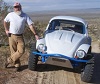
I just read your post Lee. So I went out in the dark and snapped a picture. This is the 1.75" x .120 wall roll cage upright at the B-pillar in my Baja Bug.
Yeah...I know it's dirty. That happens now and then in the life of a working Baja Bug.
Note that it fits easily on that same flat area next to the body mounting channel of the pan. You only need 1.5" tube for your buggy. You can see it does NOT set the cage tube over the bend in the pan sheet metal. It has (2) 3/8" hex head bolts fore of the upright and another 2 behind. It fits on mine and ALL VW Bug floor pans are the same in that area. No reason why you can't do that while also having a vertical panel to fasten to the inside of the body lift tube to gain so much MORE overall strength. YES...that vertical panel would need to be about 4" long. It could be welded to the horizontal base plate that bolts to the horizontal panel of the pan so that you don't need to worry about bends. Make the base plates and the doubler underneath the pan out of 3/16" plate.
You do not have the required permissions to view the files attached to this post.
Richard
Lake LA, Mojave Desert, SoCal
Speed Kills! but then...So does OLD AGE!!
Tech Inspection: SCCA / SCORE / HDRA / ARVRA / A.R.T.S. OffRoad Race Tech - MDR, MORE, Glen Helen BajaCup
Retired Fabricator
'58 Baja with 955K Miles and counting
Lake LA, Mojave Desert, SoCal
Speed Kills! but then...So does OLD AGE!!
Tech Inspection: SCCA / SCORE / HDRA / ARVRA / A.R.T.S. OffRoad Race Tech - MDR, MORE, Glen Helen BajaCup
Retired Fabricator
'58 Baja with 955K Miles and counting
-
Ol'fogasaurus
- Posts: 17758
- Joined: Mon Nov 13, 2006 10:17 pm
Re: Ol'fogasaurus black buggy
On the passenger side of the pan what you show is s/b OK but since the driver's side of the pan is not formed correctly/completely there is a problem. that is why I spend most of my time playing with it. I have taken some of the distortion out of it with a hammer and dolly but not enough yet to be OK. One area is not fixable and it definitely a weak spot.
I thought the cage was to be 1.50 dia. DOM tube but 1.75 dia. DOM tube with a 1.20 wall does sound safer. I will probably go in that direction.
Be careful with the Nyloc style of fasteners as there is a cycle limit and the nylon does have an age limit too... as I remember. It is well designed part. When it was added to the feds standard the cycle limitation was lowered a bit down to (if I remember correctly) something like 9 cycles before it was to be replaced by a new fastener. Also, if you look at the color of the material inside you can determine where it is manufactured by its color. For example, if I remember correctly a blue color is India while the more whitish color is the Nyloc company here in the US.
I am not sure I am going to be able to post pix anymore here. Photoshop is done something to my photo editing process (I've got the instruction book sitting here so I can find out how to change it to do what it was doing) and wants me to store my pix there which sounds/feels like what happened to me with my using Photobucket to post when I first got invited over here. This is where they took control of my pix I posted and wanted me to pay a very hefty storage fee and I suspect it was PB who took a lot of my original pix out of my computer and left one with their name all over it (you can find it in some of my early posts that are still here as far as I know).
Lee
-
Max Welton

- Posts: 3023
- Joined: Mon Jun 03, 2002 12:01 am
Re: Ol'fogasaurus black buggy
Lee, I just reduce my pix to 800x600 and post them directly.
Max
Max
-
Ol'fogasaurus
- Posts: 17758
- Joined: Mon Nov 13, 2006 10:17 pm
Re: Ol'fogasaurus black buggy
Thanks Max. II tried to change only the down loaded pictures or the already cleaned up versions from my camera and while I get the choices I need, what ever is going on won't allow me to change the pix size by dimensions or pixels. I wonder if someone has gotten into my computer and screwed things up.Max Welton wrote: ↑Wed Apr 20, 2022 4:22 pm Lee, I just reduce my pix to 800x600 and post them directly.
Max
Lee
I'm also having problems just posting on STF.
-
Ol'fogasaurus
- Posts: 17758
- Joined: Mon Nov 13, 2006 10:17 pm
Re: Ol'fogasaurus black buggy
The second file is the file I couldn't post the other day. It was to show how tight the supporting angle would be to the cage tube if I put a socket for it in place. If the "socket" needs to be taller then, where the thumb screw is here would be moved up higher and would not be part of the support for the mount.
Dusty might be able to give me the socket's height then there would be a bolt through there. The mount would be welded to the "socket" anyway for overall support.
Lee
You do not have the required permissions to view the files attached to this post.
-
dustymojave
- Posts: 2312
- Joined: Mon Dec 01, 2008 9:08 pm
Re: Ol'fogasaurus black buggy
IF, and I MEAN IF you DO use "sockets", they would need to be at least 3" long with the bolt at the middle of that length.
I see NO reason to use 1.75" OD tube, other than to reduce the need for a diagonal member in the B-pillar hoop.
For a cage of 1.5" OD, the sockets should be made of 1.75 x .120 DOM tube.
Is there some reason you're NOT placing the mock-up socket up against the vertical? If you're worried about the radius of the bend in the plate, you can chamfer the edge of the socket.
You previously talked about using sockets so the cage is easy to remove from the body or vice-versa in consideration of cage width relative to the inside width of the body. IF you DO use sockets, they would only reduce the overall width of the assembled cage by the thickness of the socket wall and the vertical plate. So I see no reason to go to the extra effort to use them at the B-pillar. If you need to slide the A-pillars out of the cowl, they could be of use there.
Richard
Lake LA, Mojave Desert, SoCal
Speed Kills! but then...So does OLD AGE!!
Tech Inspection: SCCA / SCORE / HDRA / ARVRA / A.R.T.S. OffRoad Race Tech - MDR, MORE, Glen Helen BajaCup
Retired Fabricator
'58 Baja with 955K Miles and counting
Lake LA, Mojave Desert, SoCal
Speed Kills! but then...So does OLD AGE!!
Tech Inspection: SCCA / SCORE / HDRA / ARVRA / A.R.T.S. OffRoad Race Tech - MDR, MORE, Glen Helen BajaCup
Retired Fabricator
'58 Baja with 955K Miles and counting
-
Ol'fogasaurus
- Posts: 17758
- Joined: Mon Nov 13, 2006 10:17 pm
Re: Ol'fogasaurus black buggy
"This is the 1.75" x .120 wall roll cage upright at the B-pillar..."dustymojave wrote: ↑Wed Apr 20, 2022 10:15 pm IF, and I MEAN IF you DO use "sockets", they would need to be at least 3" long with the bolt at the middle of that length.
I see NO reason to use 1.75" OD tube, other than to reduce the need for a diagonal member in the B-pillar hoop.
For a cage of 1.5" OD, the sockets should be made of 1.75 x .120 DOM tube.
Is there some reason you're NOT placing the mock-up socket up against the vertical? If you're worried about the radius of the bend in the plate, you can chamfer the edge of the socket.
You previously talked about using sockets so the cage is easy to remove from the body or vice-versa in consideration of cage width relative to the inside width of the body. IF you DO use sockets, they would only reduce the overall width of the assembled cage by the thickness of the socket wall and the vertical plate. So I see no reason to go to the extra effort to use them at the B-pillar. If you need to slide the A-pillars out of the cowl, they could be of use there.
Apparently I miss-read this by missing the word upright. I had planned on 1 1/2 inch tube in the first place.
I still would like the cage removable due to the body being plastic. Because of the seat being able to slide so far forward making it hard to get in and the "A" pillar being in the way of the person who would be sitting there so again, the plastic could be more easily fixed. Also, the collision side bar would need to be that far forward also.
The socket would be pinched in-between the two verticals holding it tight in the mount. I still need some additional support over the one bend unless I do use the 1.75" x .120 wall roll cage upright for the B-pillar which I probably will do. The shape of the body is still and has been the only reason for the tube being out so far towards the center. of the pan.
The 3" long is the info I needed.
Thanks, Lee
-
Ol'fogasaurus
- Posts: 17758
- Joined: Mon Nov 13, 2006 10:17 pm
Re: Ol'fogasaurus black buggy
From Dusty: "Is there some reason you're NOT placing the mock-up socket up against the vertical? If you're worried about the radius of the bend in the plate, you can chamfer the edge of the socket."
As I told you before, the lower part of the body has changed shape by moving in during the trip home on the open trailer. the body was pulled too soon from the mold and hadn't cured enough. It was done in the spring and the trip through the Cascade Mountain range did not help at all. That crummy FG work was a try to fix some of the worst change in shape and that was the mounting area over the rear cross-piece of the pan.
This is a plumb bob hanging from the inside upper flange of the body that is shaped to the inside of the body. The measurement shown on the tape is 1/4 inch.
This shows the underneath off-set. The distance shown here from the edge of the body's mounting flange to the body lift is the same as the first picture. If you move toward the front of the body the flange distance of the body to the body lift the next dimension is 3/8" then 1/2" and the spread between the measurements isn't that far. I didn't measure to find out what the worst dimension is.
I am not going to compromise the strength of the body's mounting flange any more than it already is by cutting it to match the body lift. In order to bolt the body in place I had to add some windows to the lower skirt of the body so bolts could be applied.
There still has to be a distance between the cage and the upper flange of the body. If done right the cage, even with a diagonal tube in the hoop, the cage should control some of the pan's flexing but I honestly think that is going to do that much since I can't go all the way forward with the middle tubing of the cage.
Again, my opinion!
Lee
You do not have the required permissions to view the files attached to this post.
-
dustymojave
- Posts: 2312
- Joined: Mon Dec 01, 2008 9:08 pm
Re: Ol'fogasaurus black buggy
How flush is the outside of the body flange at the body lift tube?
Is it flush?
- If Yes... Then you can cut away excess flange on the inboard side.
- If No... Then you can use a bottle jack and a 2x4 to spread the body to match to pan and drill and bolt the body flange to the pan and lift tube. Then if there is excess flange, you can trim that away.
Not sure what you mean by "I honestly think that is going to do that much since I can't go all the way forward with the middle tubing of the cage."
And WHY does there HAVE "to be a distance between the cage and the upper flange of the body"? Are you concerned the fiberglass will rub on the cage paint? You COULD put a tab on the cage to bolt to the underside of the top lip of the body to prevent scuffing from flex. I can get more specific with how to do that if you need me to.
Richard
Lake LA, Mojave Desert, SoCal
Speed Kills! but then...So does OLD AGE!!
Tech Inspection: SCCA / SCORE / HDRA / ARVRA / A.R.T.S. OffRoad Race Tech - MDR, MORE, Glen Helen BajaCup
Retired Fabricator
'58 Baja with 955K Miles and counting
Lake LA, Mojave Desert, SoCal
Speed Kills! but then...So does OLD AGE!!
Tech Inspection: SCCA / SCORE / HDRA / ARVRA / A.R.T.S. OffRoad Race Tech - MDR, MORE, Glen Helen BajaCup
Retired Fabricator
'58 Baja with 955K Miles and counting
-
Ol'fogasaurus
- Posts: 17758
- Joined: Mon Nov 13, 2006 10:17 pm
Re: Ol'fogasaurus black buggy
The body for reference.
The width of the upper flange measured on the top is 2". The inside dimension it 1/8th inch perside plus the inside radius.
This shows the inside flange 1" long minus the inside radius and the material thickness.
Assuming this is the pix I marked up:
The red dot is the pan' mounting flange, the blue dot is the 3" body lift, the yellow dot is the mounting flange of the body, the white dot is the front fender that goes back to the rear fender.
The body mounting flange is 1" below the fender and the fender, in this area is 6" wide in this area and includes a healthy radius to the body and a radius on the outside of the fender. The fender is ~90 degrees to the body (see the top picture) and pretty much controls everything in this area.
Lee
You do not have the required permissions to view the files attached to this post.
-
Ol'fogasaurus
- Posts: 17758
- Joined: Mon Nov 13, 2006 10:17 pm
Re: Ol'fogasaurus black buggy
Other than looking at the buggy as I walk by it (and that is often) I haven't done much physical stuff on it for a while.
I've moved to the front of the buggy where the A-hoop of the cage should be.
This is the firewall area of the buggy, and it shows the cowl area where the firewall is. Years ago, we tried to do some fiberglass work but for some reason it didn't work and looks like &%@#*! One of the things to notice is that there is an input break in the buggy wall and a "reverse" piece is added for support (I think). This piece is the area where the windshield frame would be added (the inside of it will be shown in the next 2 pix).
The white line on the body lift is where the side (crash) bar is to be added.
On the cowl there is a piece of tape cut into a oval showing roughly where I think the opening for the front hoop will access.
This is on the inside of the body. Notice that the hoop piece is sitting on the doubler for the (kerfed) body lift. The mount for the hoop will be attached to the body lift and floor by bolts. The bolts to the body lift will go through the body lift (via. tubes to keep salt sand and salt water from seeping in as much as possible). The bolts will also hold the mounts for the side (crash) bar.
I don't like the idea of the bolts through the kerfing even though there is a healthy doubler to back them up.
A closer look at the inside of the buggy and you can see the helter-skelter of the FG on the inside.
If the hoop is touching or nearly touching the piece of FG for the windshield, then the tape hole is pretty close.
Lee
You do not have the required permissions to view the files attached to this post.
-
dustymojave
- Posts: 2312
- Joined: Mon Dec 01, 2008 9:08 pm
Re: Ol'fogasaurus black buggy
You're making good sense here Lee. The base of this A-pillar is where I recommend using a socket of 1.75 x .120 wall tube welded to the base plate with a through bolt to fasten the roll cage upright into it. I recommend it here because the cage will be passing through the cowl, so any flange on the bottom would not be removable.
I know I'm looking at mock up, but I recommend adding about 1/2" to the final flange front and back edges, while reducing how far towards the tunnel the flange extends. Since the strength of the pan is at the edge in the formed channel for body mount bolts, combined with strength of the body lift tube, going further out onto the sheet metal pan adds very little strength. One bolt up through the pan sheet metal in front and one behind the A-pillar, with a doubler plate underneath, will do well to fasten the cage to the pan. Bolts through sleeves welded into the body lift will in NO WAY weaken the already way stronger than necessary body lift tube. Those flanges/base plates and doubler plates should, as discussed before, be made of 3/16" cold roll 1010 steel plate. If bending that plate is a problem for you, just use 2 flat plates and weld them along the seam where the bend would be.
I approve of using the roll cage bolts to mount the side nerf bars.
This is the 1st time I've seen the steering brake handles next to the shifter from this angle. Have you tried those out? I suspect trouble with interference between the brake handles and the shift lever. You may want to sit in the car and try pulling those handles (while making "Vroom - Vroom" noises!). I know the brakes aren't plumbed so there won't be the normal resistance. To reduce interference, you could bend the handles outward maybe 20° a little behind the shifter housing. You don't want to bend them too far out and start trouble with the seats that will already be rather close.
Richard
Lake LA, Mojave Desert, SoCal
Speed Kills! but then...So does OLD AGE!!
Tech Inspection: SCCA / SCORE / HDRA / ARVRA / A.R.T.S. OffRoad Race Tech - MDR, MORE, Glen Helen BajaCup
Retired Fabricator
'58 Baja with 955K Miles and counting
Lake LA, Mojave Desert, SoCal
Speed Kills! but then...So does OLD AGE!!
Tech Inspection: SCCA / SCORE / HDRA / ARVRA / A.R.T.S. OffRoad Race Tech - MDR, MORE, Glen Helen BajaCup
Retired Fabricator
'58 Baja with 955K Miles and counting