Page 1 of 2
Understanding Wiring
Posted: Tue Jul 31, 2007 12:54 pm
by david58
Posted: Tue Jul 31, 2007 3:45 pm
by MNAirHead
Submitted by David58
A real big thanks to Speedy Jim for letting us link to his Electrical Wiring Section. If you haven't had a look around his site click the link below.
http://www.nls.net/mp/volks/
Wiring property of Speedy Jim
Brake Lights/Tail Lights
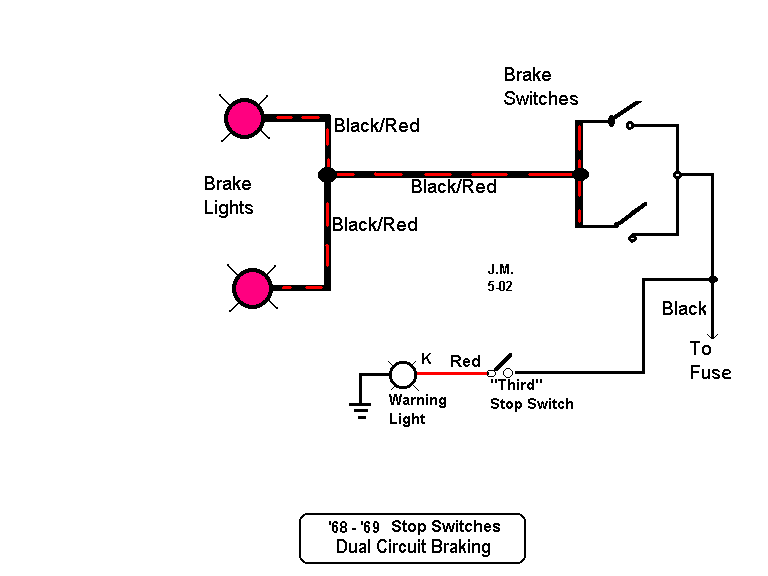
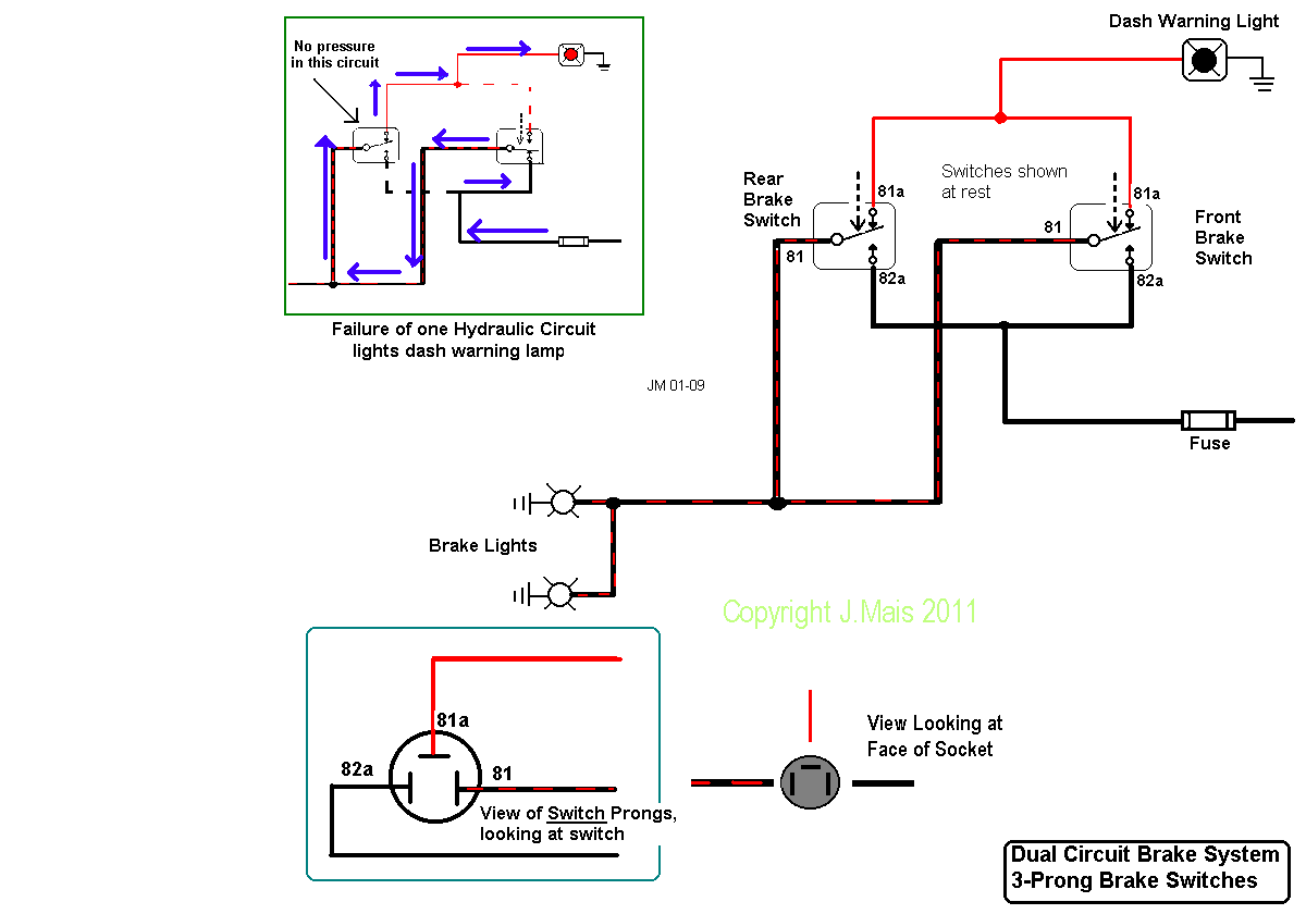
Wiring of 2-prong brake light switches ('68/'69) with 3rd switch for warning light.
Wiring of 3-prong brake light switches ('70 and later) with warning light connection.
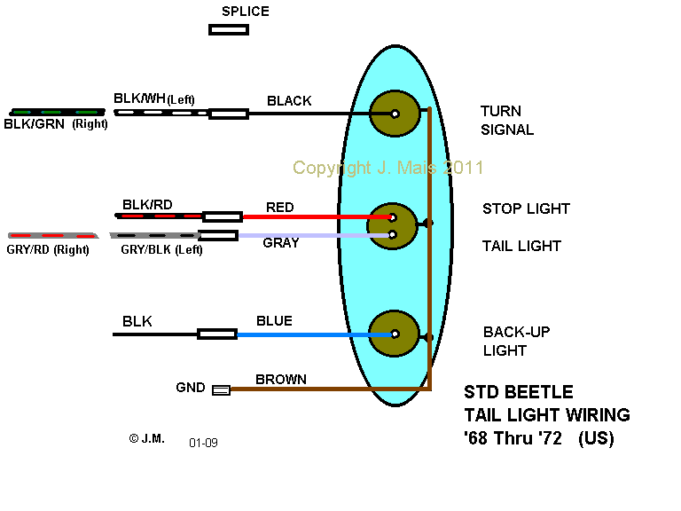
Tail light wiring: '68 thru '72 Beetle
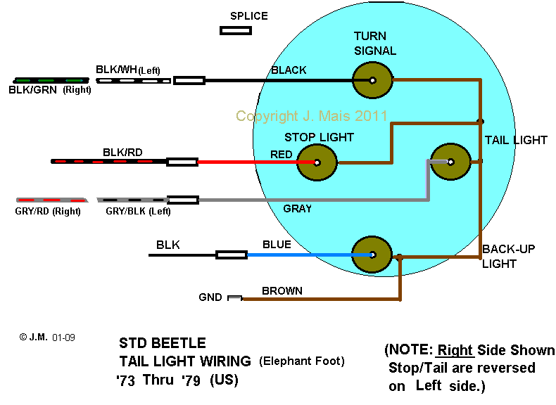
Tail light wiring: '73 thru '79 Beetle
Headlights
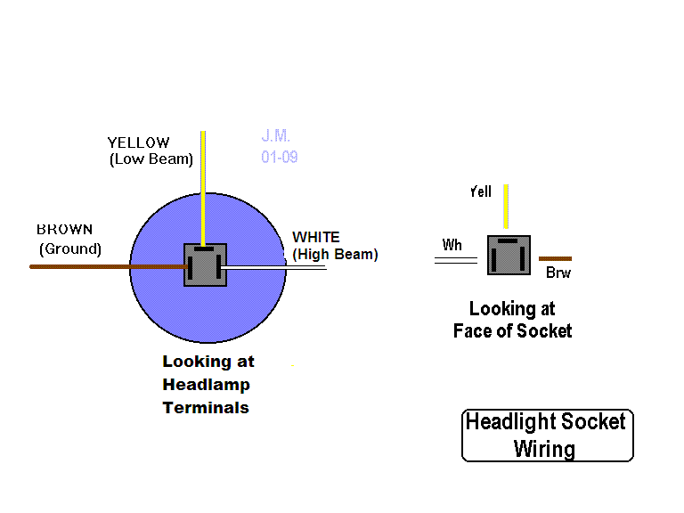
Wiring of the headlight sockets.
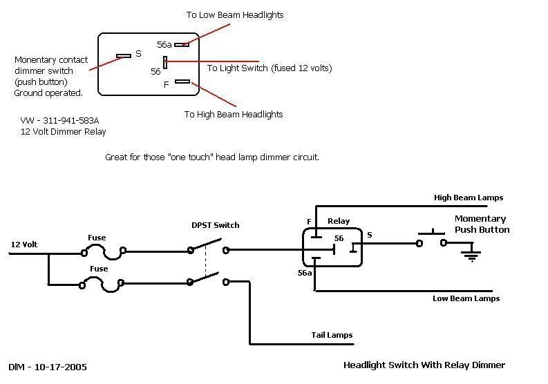
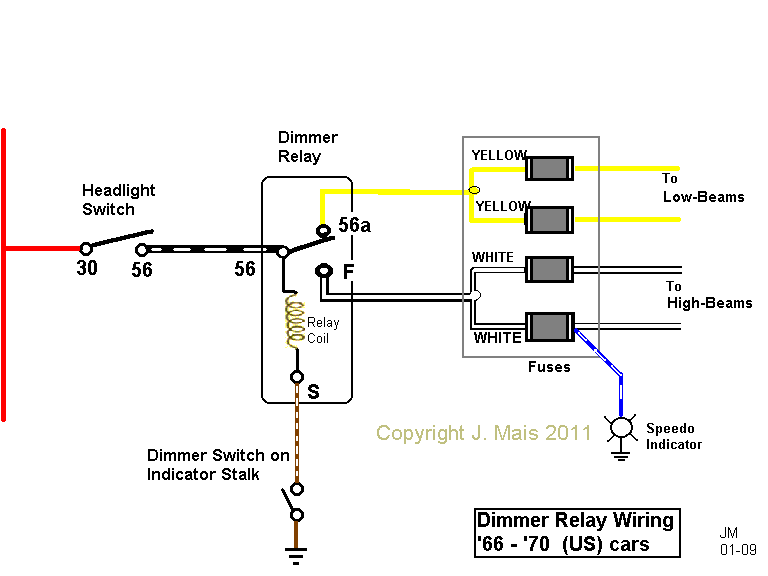
Headlight dimmer relay circuit '67 thru '70.
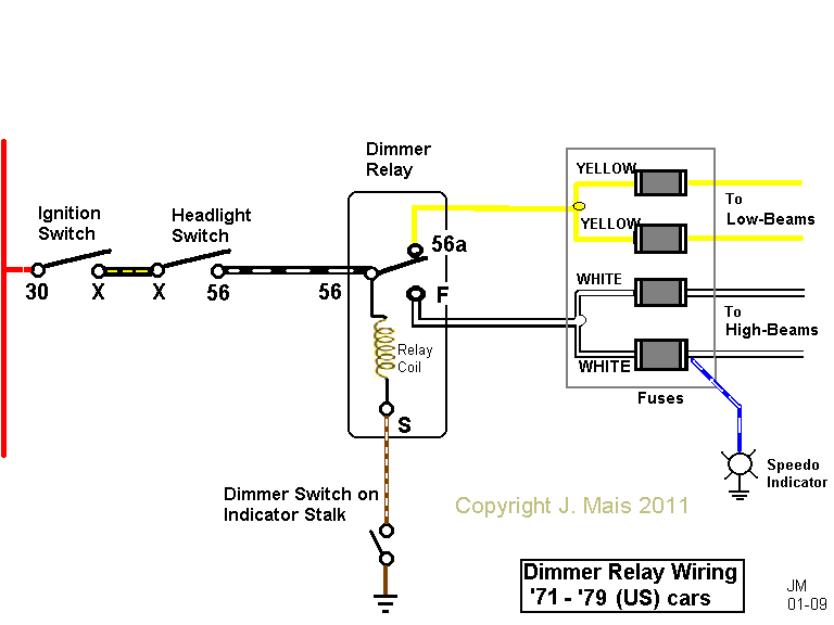
Headlight dimmer relay circuit '71 thru '79.
Fuel Injection
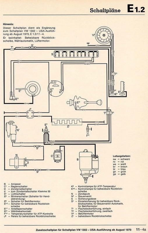
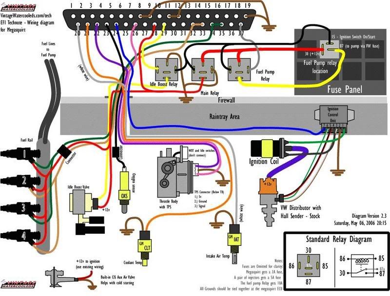
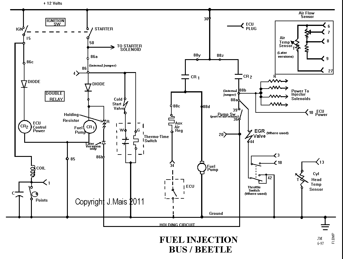
Schematic of Fuel Injection system, '75 -'79 Type I and Type II.
Description of Fuel Injection circuit, '75 -'79 Type I and Type II.
Windshield Wipers
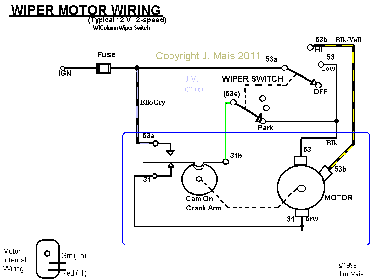
Wiring of 12 Volt, 2-speed wiper (Steering column-mounted switch).
Description of circuit for 12 Volt, 2-speed wiper (Steering Column-mounted switch).
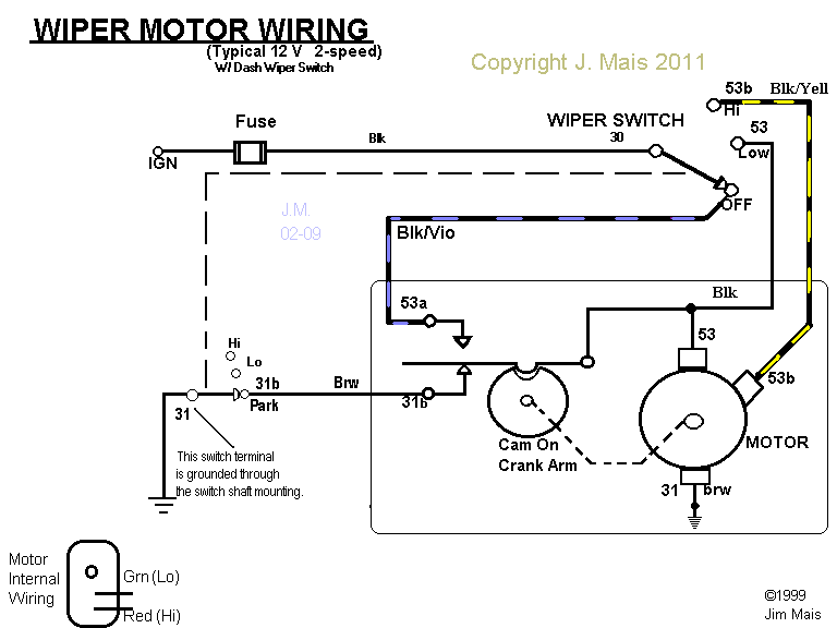
Wiring of 12 Volt, 2-speed wiper (dash-mounted switch).
Description of circuit for 12 Volt, 2-speed wiper (dash-mounted switch).
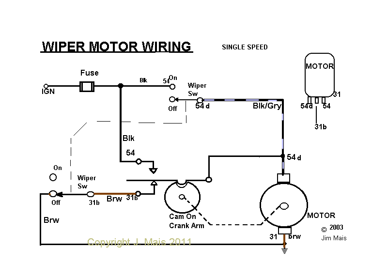
Wiring diagram for 6V Single-speed wiper.
Wiper wiring (Pdf) on '71 Transporter (stock)
'71 Transporter - Adding Wiper Delay circuit (Pdf): Provided by Michael Elliott
Alternators/Generators
How do I test my Generator ?
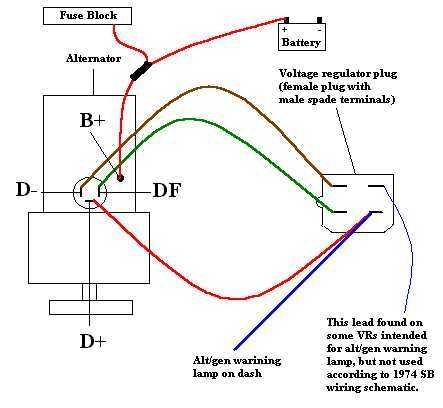
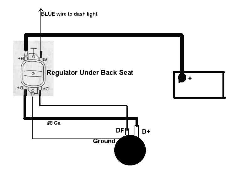
Generator to Regulator wiring.
6V To 12V Conversion - Check List
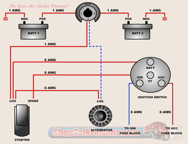
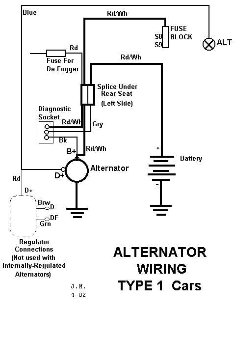
Wiring diagram for Type I cars with alternator.
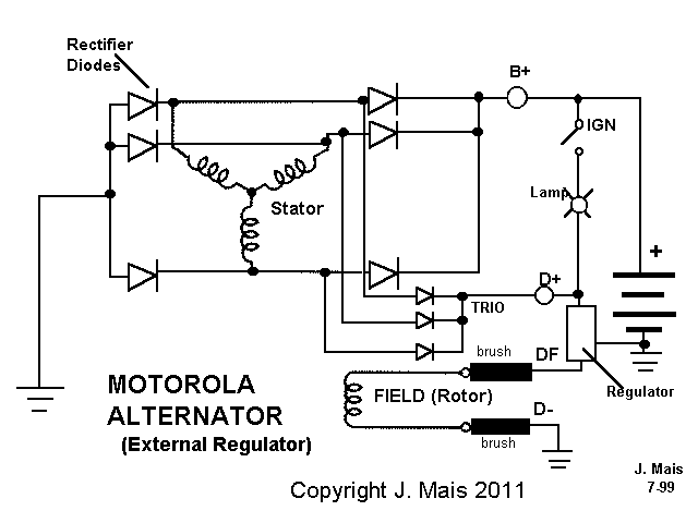
Wiring details for Type I alternator with external regulator (Motorola).
Description of Alternator operation.
Internal wiring of Motorola Alternator w/ external regulator.
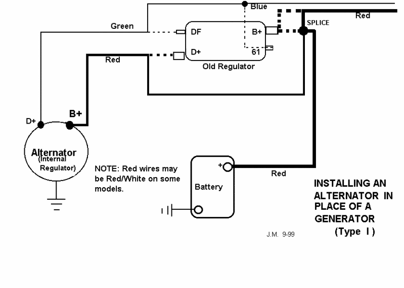
Wiring for conversion from Generator to Alternator.
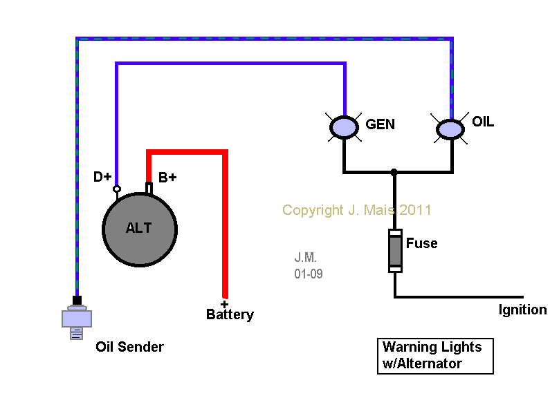
Adding a dash warning light to a Buggy with Alternator.
How to test for excessive "drain" on the battery.
Miscellaneous
What is this plug in my engine bay?
Using a 3-wire turn signal switch with single-bulb tail lights .
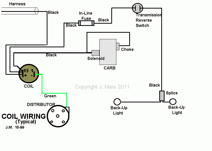
How to wire the carb (choke and solenoid) to the coil.
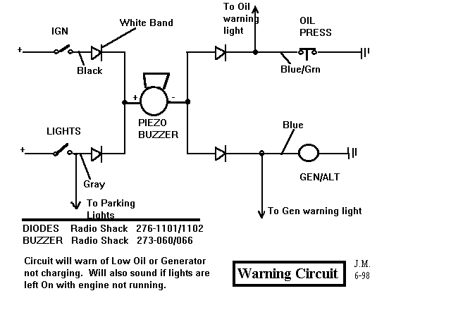
Audible warning circuit for Oil pressure, Generator, Lights left on.
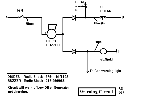
Audible warning circuit for Oil pressure, Generator.
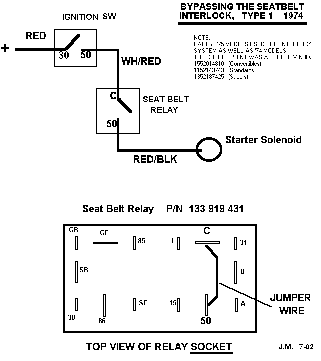
Starter /seatbelt interlock wiring on '74 Type I (How to bypass it.)
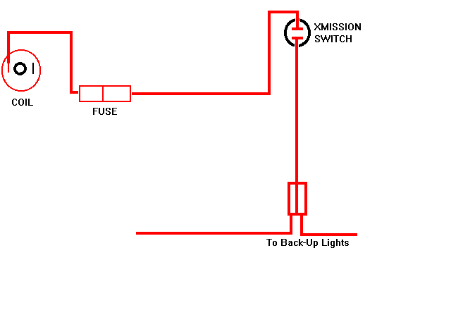
Wiring of backup lights.
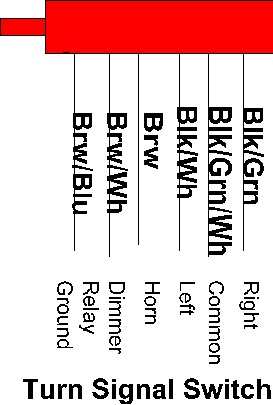
Wiring of plug for Turn Signal switch ('72 Up)
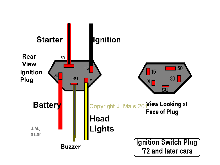
Wiring of plug for Ignition switch ('72 Up)
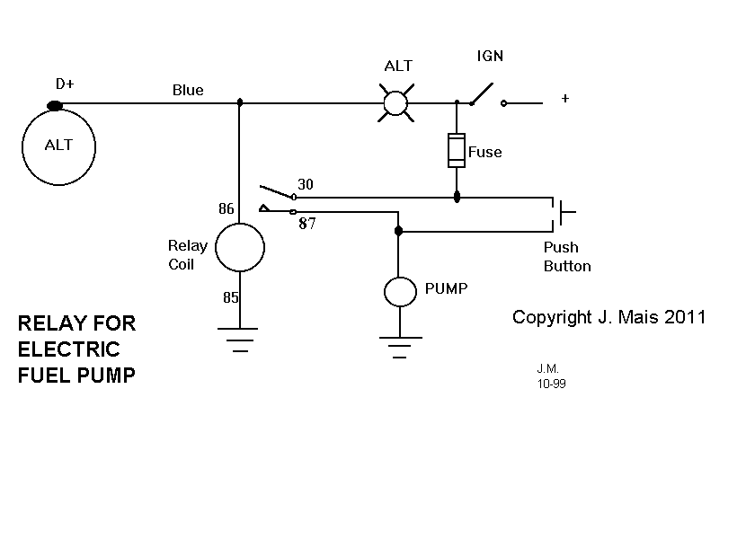
Safety circuit for adding an electric fuel pump.
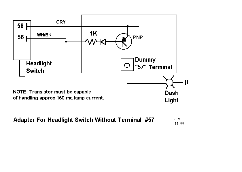
Circuit that simulates Term #57 on the Type II Headlight switch.
9-Terminal Flasher explained. This is a Link to the page written by Matt Roberds.
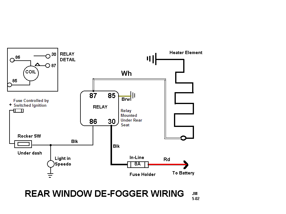
Circuit diagram for rear window defogger on Type 1 cars.
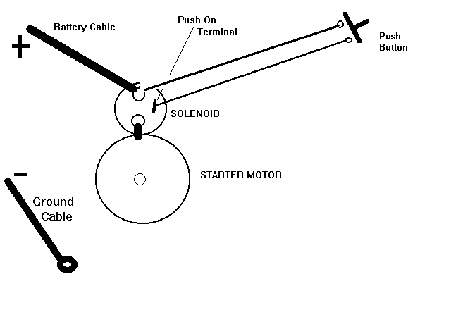
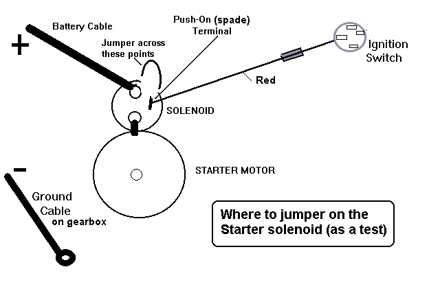
Where to jumper on the starter solenoid to test starter.
3-terminal 12V flasher, simplified wiring diagram.
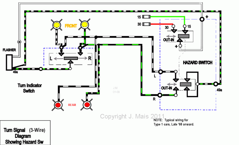
3-terminal 12V flasher, simplified wiring diagram showing 4-Way Hazard switch: '72 and later.
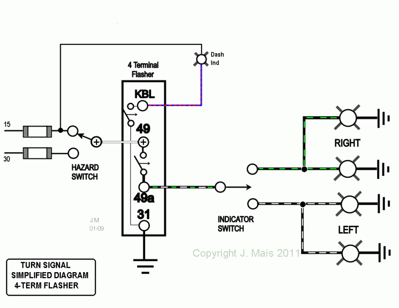
4-terminal flasher used on late '68 thru '71, simplified circuit.
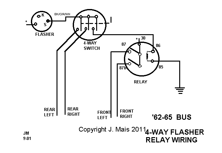
'62-66 BUS 4-Way hazard switch and relay.[/quote]
Re: Understanding Wiring
Posted: Fri Apr 25, 2008 7:18 pm
by Dodahsand
It was there and now, I can not seem to find it... I'm looking for a schematic that shows how to correctly re-wire a sandrail. I know it's here somewhere and after looking for one hour I am begging for your forgiveness.
What I am doing is re-wiring a Johnny Speed or Fugitive frame I just bought. Everything is hard wired with no fuse blocks or relays. Everything has been ran through the frame through drill holes. I'm going to pull every wire and re-do the whole thing. Adding a fuse block and relays for 2 55 watt floods, two 100 watt floods and two 55 watt driving lights. Currently I have a 14 volt 50 amp alternator. The schematic that i'm looking for showed proper routing, connection and wire gauge. Also it showed each option and it's out put.
Electric fuel pump = so many amps
gauge cluster = so many amps
flag and rear lights = so many amps.
I want to do this right. Can you help ? [andquote="David58bug"]
Leatherneck wrote: What helps me a lot is having a schematic or drawing to show me what goes where. Maybe some others have a better idea but I like to draw out where headlights, relays, tailights, switches etc. go before I start running wire. So if anybody has any schematics,diagrams or drawings that you use that might be helpful to others post them up.
Here are some wiring schematics and diagrams that you may or may not use. Don't think copywright is a problem.
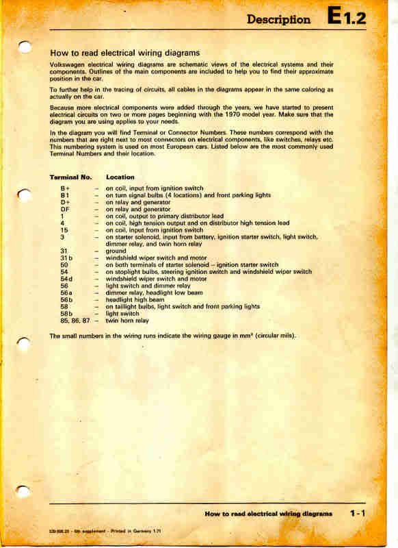
Understanding and reading wiring diagrams
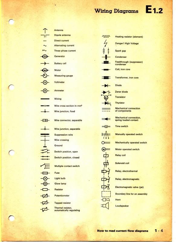
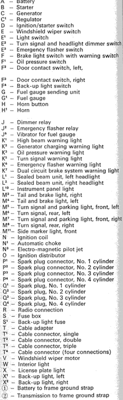
What do all those symbols, letters, and numbers mean on the diagram.
What do those Symbols Mean?
How do I Read a Diagram?
How are the Components Labeled on a Diagram?
Wiring Diagram Legend
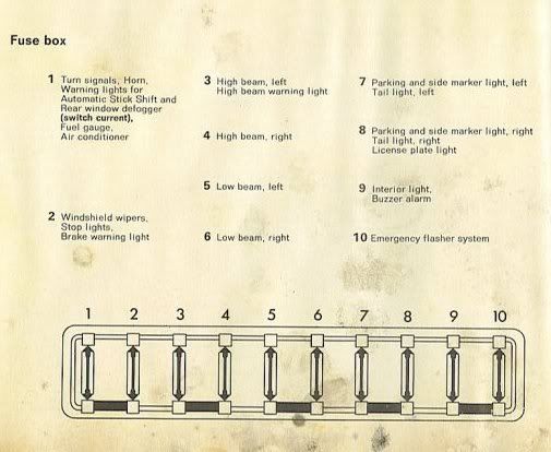
Typical Fuse Box Layout
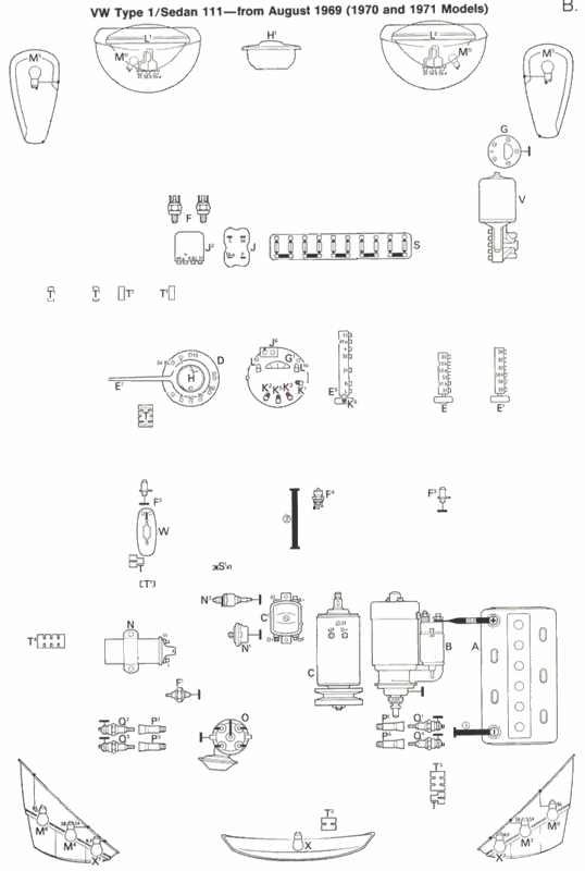
Wiring Diagrams Posted by Leatherneck
Fuel Pump Relay
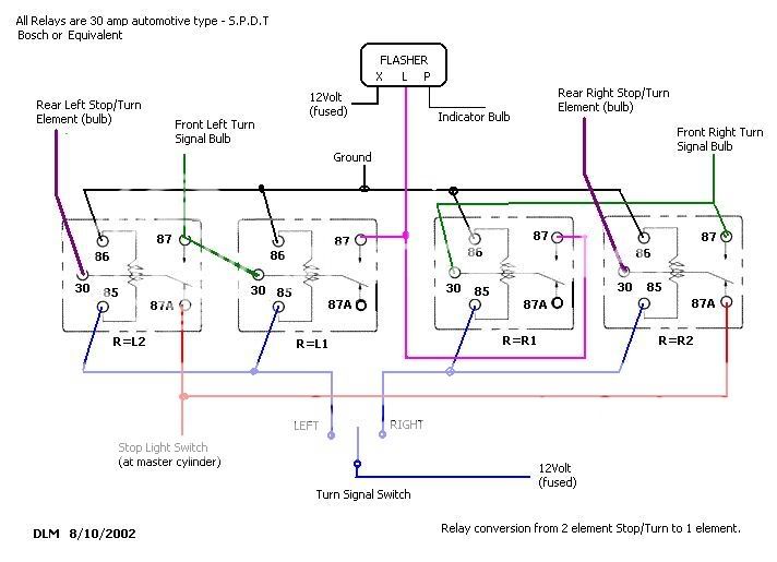
Relay conversion from 2 Element Stop/Turn to 1 Element
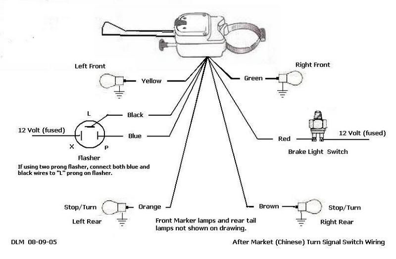
Aftermarket (Chinese) Turn Signal Wiring
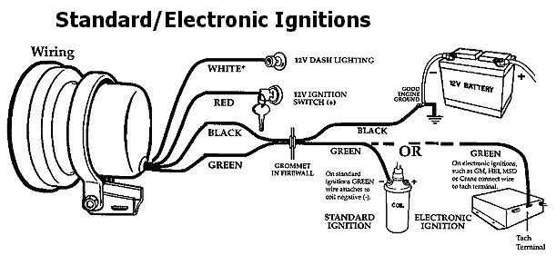
Tach Wiring for Standard Electronic Ignition Systems
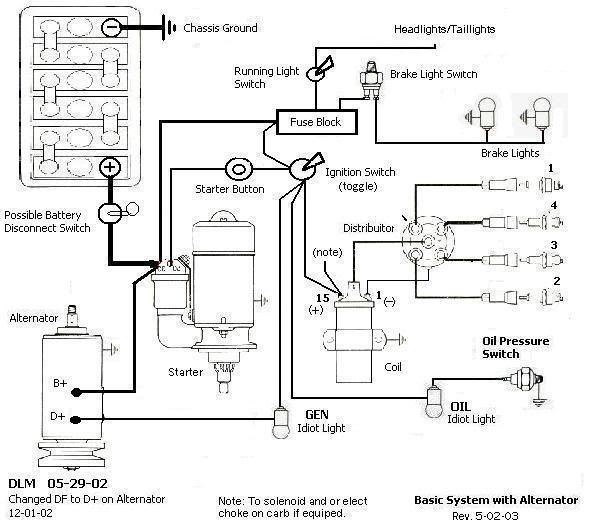
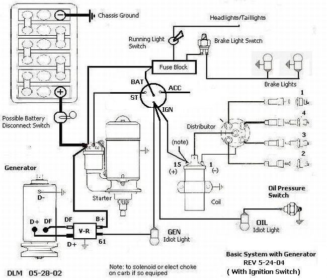
Basic System with Alternator & Toggle Ignition Switch
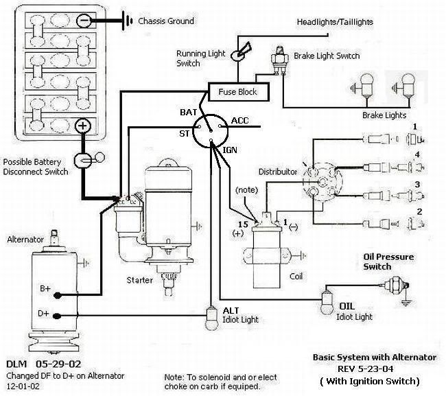
Basic System with Alternator with stock Ignition switch
Regulator Wiring for Generators
Headlight Relay for Dimmer
Wiring for Generators
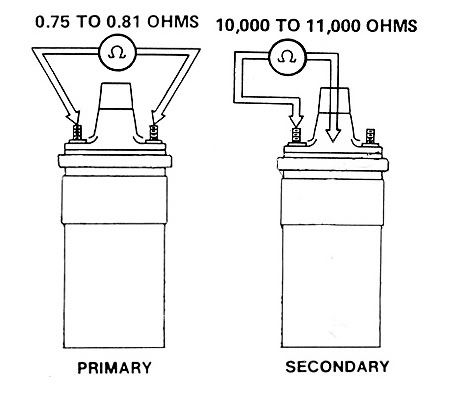
How to OHM out a Ignition Coil
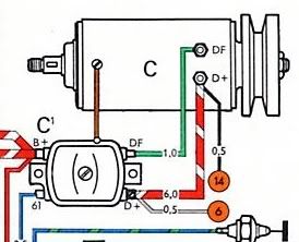
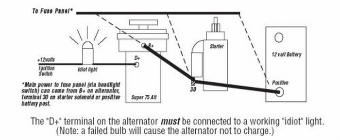
Basic Alternator Wiring
4 Wire Alternator Wiring
Posted by David58bug
Basic Power Circuits
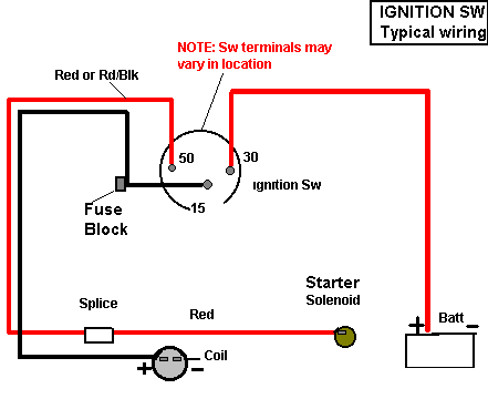
Ignition Circuit
Starter Circuit
Charging Circuit VW
Turnsignal Circuit VW
Brake Lamp Circuit VW
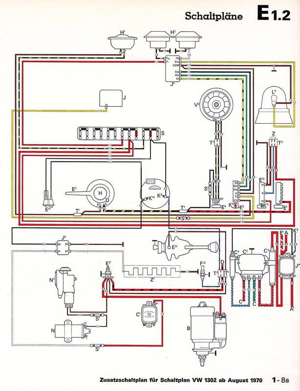
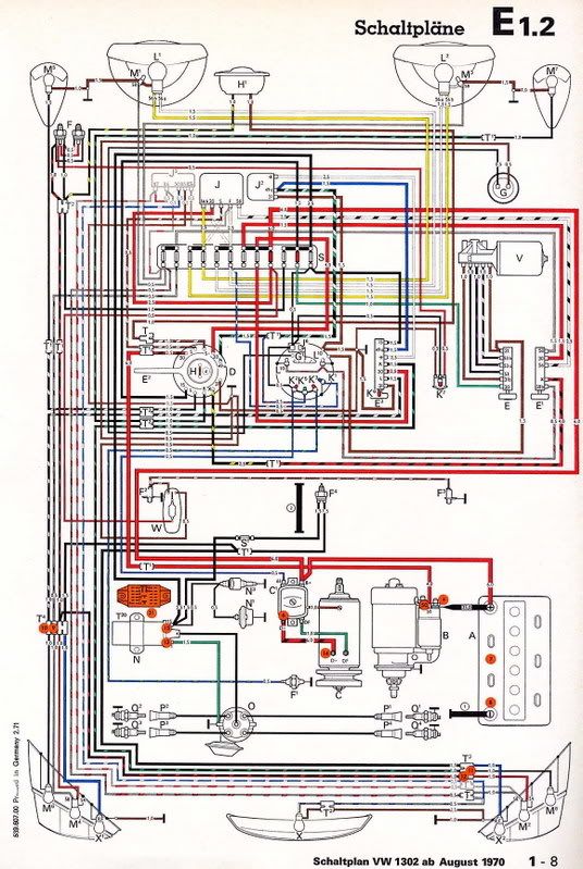
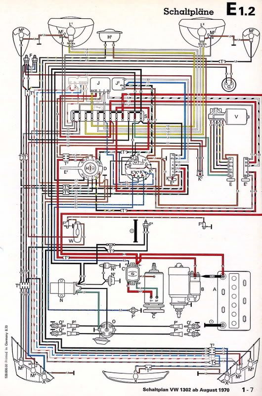
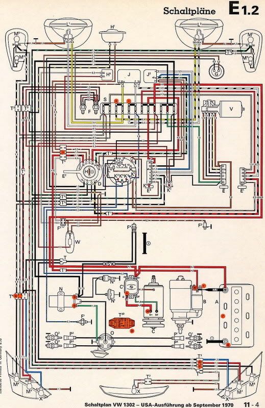
1302Wiring Diagram
WiringDiagram1
WiringDiagram2
WiringDiagram3
WiringDiagram4
WiringDiagram5
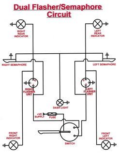
SemaphoreTurnSignalWiring
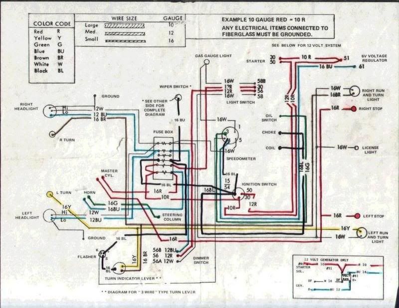
Typical Buggy Wiring Diagram
EFI Wiring Diagram
Starting Motor Trouble Shooting Chart
Posted by Panel
Alternator Wiring Guide
Posted by MnAirhead
Generator to Alternator
71 Wiring Loom
Outback Wiring Diagram
Posted by SpeedyJim
Starter Wiring
Alternator Wiring
Ignition Wiring
FI Wiring
Turn Signal Wiring
Posted by DesertGuy
WildKids Wiring
Primary Circuit Wiring[/quote]
Posted: Fri Apr 25, 2008 7:23 pm
by david58
Posted: Sat Apr 26, 2008 3:37 am
by slowtwitch
What a great site and it's people like you, Dave, that make it great. Thanks for all that you do

Posted: Sat Apr 26, 2008 4:18 am
by MNAirHead
Slow..
You're totally right.. we're blessed to have some of the tenured folks and information organizers here.
Combining this with the abiltiy to ask any question does make this the aircooled haven.
We appreciate all contributions.
Posted: Sat Apr 26, 2008 4:33 am
by Dodahsand
Thanks Dave for the schematic. I tied everything together. I have two questions. As far as knowing what each amperage my equipment has. I know my lights amperage and wattage.
How do I figure my...
Triple gauge amperage and wattage
Electric fuel pump
Flag and back lights
Tach
Is the amperage important info when calculating what size fuse and fuse box to use ?
And, slowtwitch, your right. This is a great site. Never any criticism.
Posted: Sat Apr 26, 2008 4:34 am
by david58
rickosuave1987 wrote:I thought this might be of some help to the guys running after market lights and such. I have seen quite a few questions in the Off road forum too.
Wire sizing.
Typically you want to size your wire for 125% of the load it is going to handle.
So if you have 5 amps on the circuit, you want to size the wire for 6.25 amps.
here is a chart with wire capacities
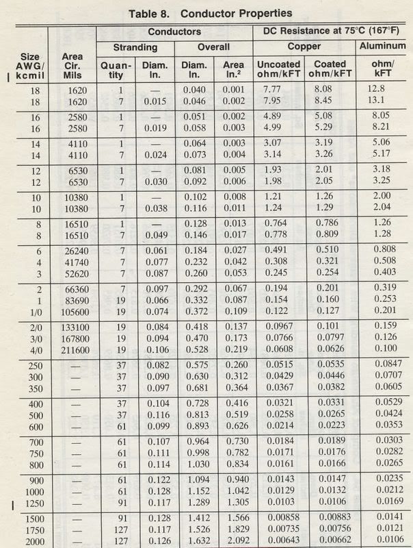
Some equations:
AMPS
watts/voltage=amps
VOLTAGE DROP
(AMPS x FEET x 21.6) / Cir Mills
Circular mills can be found on the chart above.
(Voltage Drop/volts)x100 = % voltage drop - usually you want this to be below 3% for everything to function properly.
Posted: Sat Apr 26, 2008 4:39 am
by Dodahsand
WOW... Now that was fast. Looks like your an early riser too. Thanks for all of your help. I'm new to the VW - Buggy seen. I just want to do this right.
Posted: Sat Apr 26, 2008 4:40 am
by david58
slowtwitch wrote:What a great site and it's people like you, Dave, that make it great. Thanks for all that you do
You guys better watch out I have two computers running now.

I have been using a Dell made in 1999.

I bought an e-machine at the pawn shop with XP on it. I cleaned the harddrive and got it purring like a kitten.
It was a big battle, but I think I won the war with then viruses.
Posted: Sat Apr 26, 2008 4:42 am
by david58
Dodahsand wrote:WOW... Now that was fast. Looks like your an early riser too. Thanks for all of your help. I'm new to the VW - Buggy seen. I just want to do this right.
I am the STF BOT I never sleep.
Posted: Sat Apr 26, 2008 4:44 am
by Dodahsand
I understand everything in the first and second charts. See the second chart, see the forth line "So if you have 5 amps on the circuit, you want to size the wire for 6.25 amps". How do I know if I have a 5 amp circuit ? How do I determine my circuit amperage ? That is my question. Once I understand that, i'm off to the parts place.
Posted: Sat Apr 26, 2008 4:50 am
by MNAirHead
Do you have an ohm meter (or VDO type ammeter).. you could measure before/after current - OR add up the devices on the circuit.
I'll leave hooking up an ohm/amp meter to a smarter guy.
Posted: Sat Apr 26, 2008 4:56 am
by Dodahsand
Yeah, I have a cheap meter that can do that. Just fire up the buggy and get a reading from the open circuit.

Posted: Sat Apr 26, 2008 4:56 am
by david58
Dodahsand wrote:I understand everything in the first and second charts. See the second chart, see the forth line "So if you have 5 amps on the circuit, you want to size the wire for 6.25 amps". How do I know if I have a 5 amp circuit ? How do I determine my circuit amperage ? That is my question. Once I understand that, i'm off to the parts place.
You have a couple choices. Call the manufacturer, or check the amperage of each component. Your going to want to put your meter in SERIES with what you want to measure. Example: If you want to test the current pull of a Circuit you would put the + probe of your meter to the + side of your power supply & the Neg probe would go to the + side of the circuit. Most multimeter only have 10 amp max, so if the circuit pulls more than 10 amps the fuse blows in the meter.
