Posted: Sat Sep 05, 2009 2:47 pm

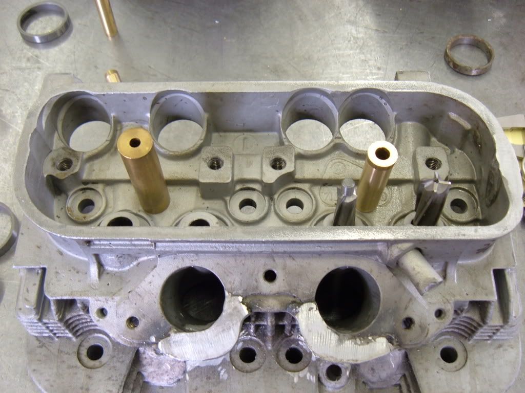
But the the tolerance you use when you fit the guides probably won't be the same before and after you cut the hole for the valve steam! Just one more thing to considerGetbackontrack wrote:Actually im thinkin about pushing in homemade guides "with no hole for the valve stem" and then put the head up in the same jig that I used for cutting the holes for the seat, center the inside seat area and cut the holes for the valve stems. That way im absolutely sure that the valve head is concentric with the seat.
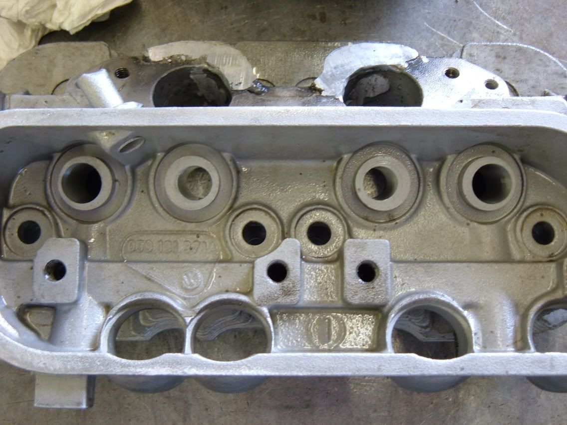
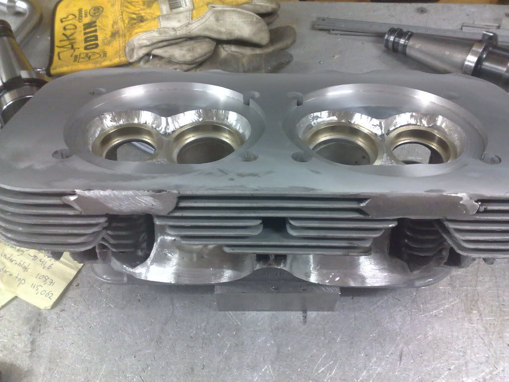
Getbackontrack wrote:Today I got the old guides out and cut the chamber to accept 105 mm pistons and barrels. I have only cut down 0,2 mm in the surface. The whole idea with the welding of the chamber was to be able to get the compression I needed without cutting down in the chamber. Now I need to grind the chambers to the desired cc.
Hey Richard, I really cant see your point. You cant deside the position of the seat weather you use an old guide or new guide for "centering" What desides the position of the seat is how the hole in the head is cut (and of which variables the hole is centered from).
If you want to be sure you would have to put in new guides before you cut the hole for the new seat. But who wants to put in new guides to cut a seat hole for thereafter pushing them out again for proper porting and be in the same position again?
Actually im thinkin about pushing in homemade guides "with no hole for the valve stem" and then put the head up in the same jig that I used for cutting the holes for the seat, center the inside seat area and cut the holes for the valve stems. That way im absolutely sure that the valve head is concentric with the seat.
Like you mention yourself there are to many variables. This way is (the way I see it) the only way to be sure its done right.
Regards, Jakob
I know you don't see my point, and thats OK...Hey Richard, I really cant see your point.
Here you are wrong for several reasons and one being a factor that you haven't considered. And this factor that I hadn't mentioned, and wouldn't have been an issue, had youYou cant decide the position of the seat weather you use an old guide or new guide for "centering" What decides the position of the seat is how the hole in the head is cut (and of which variables the hole is centered from).
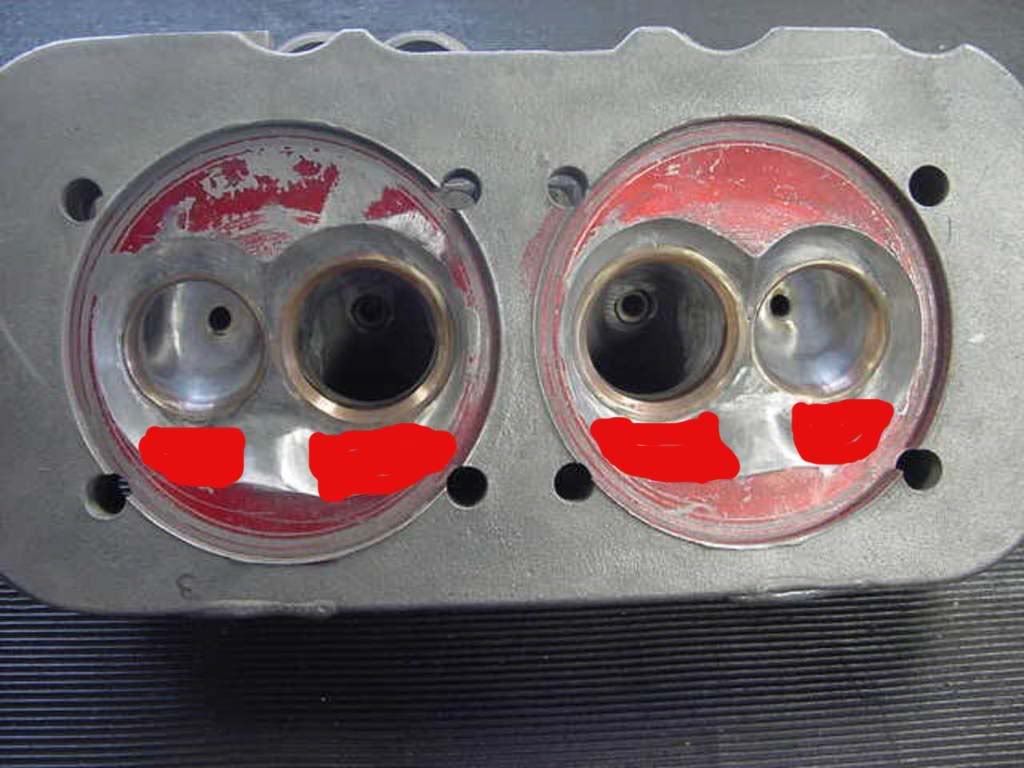
The valve guides were relocated wider to make room for the larger valves, the 914 2.0 ltr Exh guide was used for the Int and the Bronze material was
used to make even a larger Exh guide.
And when you do the welding on your heads weld up that little area between the ports over from the center manifold stud. And watch how much you weld in
between the ports, remember you have to get an extension with a socket by the ports to tighten up the head studs, bottom pic.
Actually im thinkin about pushing in homemade guides "with no hole for the valve stem" and then put the head up in the same jig that I used for cutting the holes for the seat, center the inside seat area and cut the holes for the valve stems. That way im absolutely sure that the valve head is concentric with the seat.
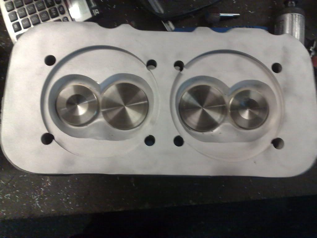
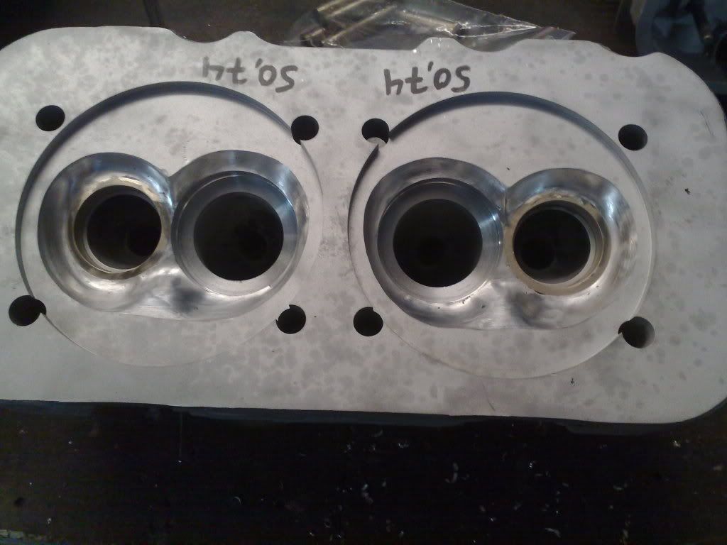
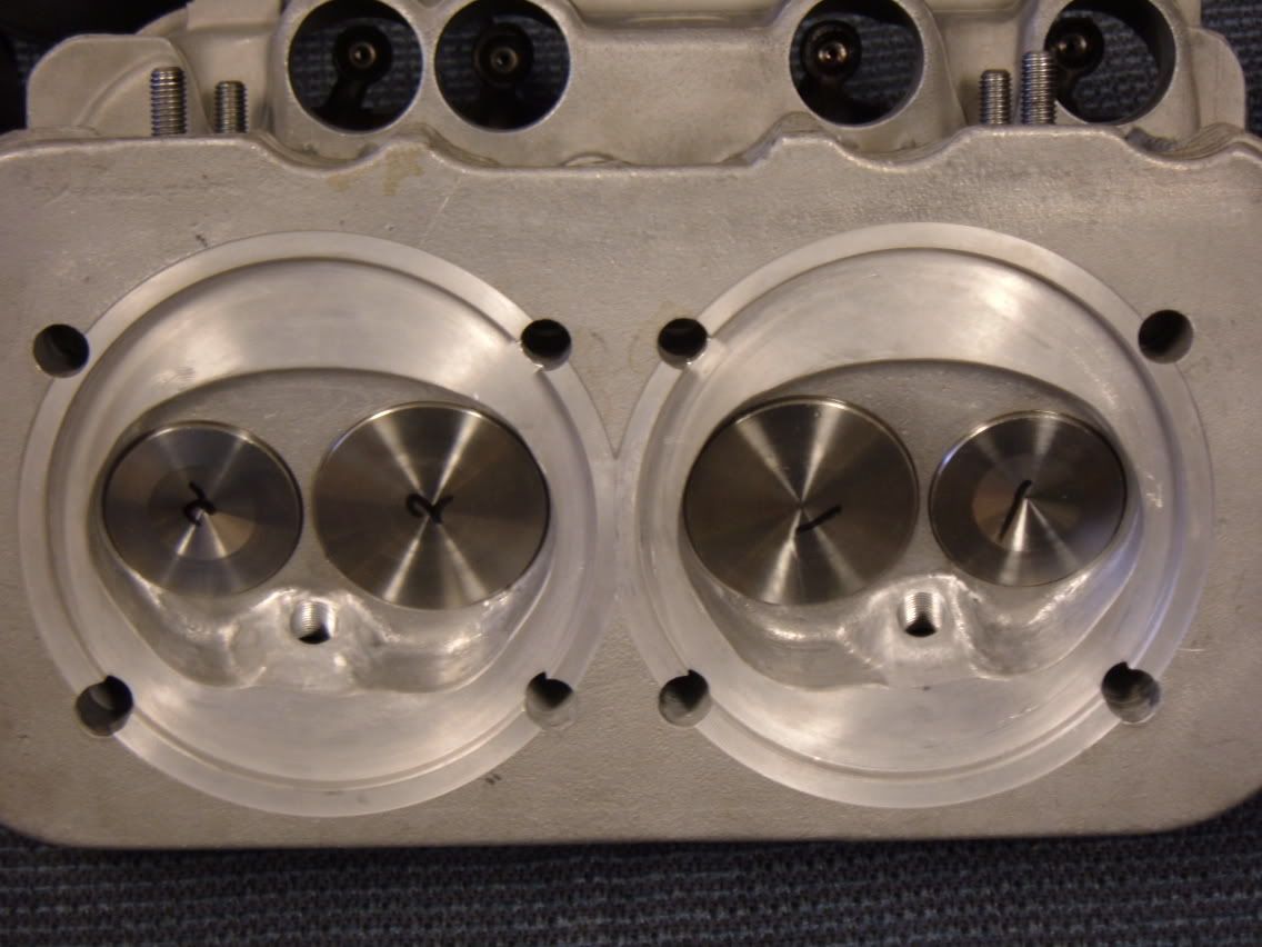
Hi JakobGetbackontrack wrote:Couldnt resist the fact that it actually was possible to install a 50 mm inlet valve, so cut new holes for the seat to the 50 mm valve also
Regards, Jakob
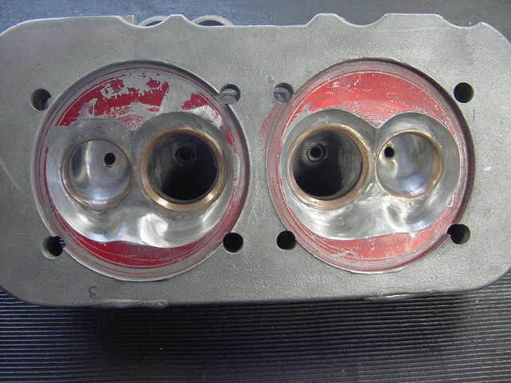
Why?drilled & tapped the holes for the spark plugs before any contouring was done around the plug boss.
If you don't know where the hole is, then how can you shape the boss around the hole that isn't there ? Well I did and wish I would of drilled the hole first, would of made it much easier.Clatter wrote:Why?drilled & tapped the holes for the spark plugs before any contouring was done around the plug boss.