Getting closer now. This isn't going as fast as I expected it to...big surprise.
I ordred my crank fire system from CB, along with the fuel rails for the high flow endcastings, ordered a fuel regulator and pump from Amazon, and now im just searching for Coils.
I also purchased my first house, and having the space to do all of my work really makes a big difference.
Hopefully in the next week or so, I can bring the Beetle inside and have a nice long hibernation for Her as I begin the turbo transformation. Slowly but surely here.
MS3v3 System for CNP and EFI/Turbo "Beetle"
-
kangaboy

- Posts: 1036
- Joined: Wed Jan 22, 2003 12:01 am
-
Clonebug
- Posts: 4745
- Joined: Thu Feb 15, 2007 9:28 pm
Re: MS System for CNP and EFI/Turbo - MS3v3 "Gathering Parts
Nothing wrong with slow.....I gathered parts for a couple years before I went turbo.....then another 2 years before I went to FI.
Stripped66 wrote:The point wasn't to argue air temps with the current world record holder, but to dispel the claim that the K03 is wrapped up at 150 HP. It's not.
-
aircooledtechguy

- Posts: 1709
- Joined: Sun Oct 28, 2001 1:01 am
Re: MS System for CNP and EFI/Turbo - MS3v3 "Gathering Parts
X2Clonebug wrote:Nothing wrong with slow.....I gathered parts for a couple years before I went turbo.....then another 2 years before I went to FI.
I began acquiring parts in 2009 for the 2316cc motor I now have. . .
Good things come to those who wait,. . . patiently.
-
kangaboy
- Posts: 1036
- Joined: Wed Jan 22, 2003 12:01 am
Re: MS System for CNP and EFI/Turbo - MS3v3 "Gathering Parts
Moving along again. Home projects never seem to come to a hault, but trying to find time here and there.
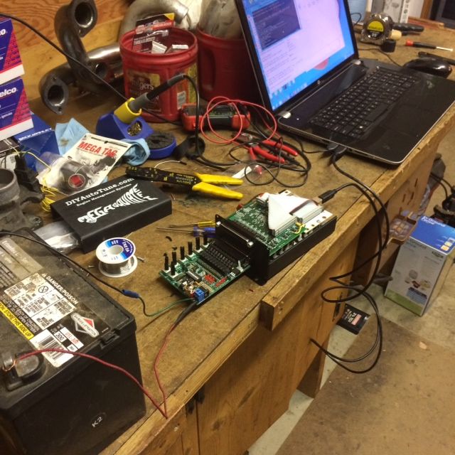
Just completed building the MS3, and after a while of figuing out what programs, drivers and firmware to put on my computer and the MS3, I finally got it flashed and connected to my laptop. It's a big step for me...actually building this and having the success of it "talking" to my laptop was a big win (Turning knobs on the jimstim and seeing the gauges react on my laptop was so cool).
(Before you say anything, I'm getting fused lines on the way home from work today)
I went with the ACDelco truck coils that I found on Ebay. They have the right part numbers and came with pigtails.
I have everything on my list marked off parts wise, so I'm about to back the bug into the garage for the winter and take 'er motor out to start hooking up the EFI system and installing the turbo.
-
kangaboy
- Posts: 1036
- Joined: Wed Jan 22, 2003 12:01 am
Re: MS System for CNP and EFI/Turbo - MS3v3 "Gathering Parts
Bought a bag of wiring and fuse materials from Autozone during my lunch break, and now I'm just looking forward to getting home and wiring stuff up. I have been reading over MSExtra manuals for days now...and really learning a lot from them and the forums.
Four quick questions:
1) I will be running batch fired/wasted spark until I get one of Mario's cam sensors. I wanted to wire up the injectors and coils separate from one another now, so when I switch over to sequencial I won't have to do any rewiring. Is this acceptable? Or will they have to be wired together for now?
2) I have an air temp sensor, and a coolent temp sensor...where will the actual sensors go in the system to give relavent readings? (I assume the air temp sensor goes in the intake prior to the throttle plate, but idk about the coolant temp)
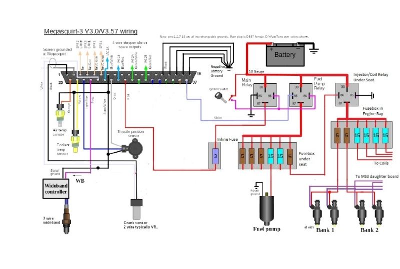
3) Looking at the suggested megasquirt wiring diagram, they have two relays. One is for 12v to the megasquirt, and one is for the fuel panel containing the injectors, fuel pump, and wideband. Why do we need two? Why shouldn't i just have one relay supplying power to all of them including the MS?
4) Lastly, with the 6 fuse panel that I bought, can I have #1 and #2 injectors and coils getting 12v from one post, and #3 and #4 injectors and coils getting 12v from another? Or do they need to all have their own fuse?
Four quick questions:
1) I will be running batch fired/wasted spark until I get one of Mario's cam sensors. I wanted to wire up the injectors and coils separate from one another now, so when I switch over to sequencial I won't have to do any rewiring. Is this acceptable? Or will they have to be wired together for now?
2) I have an air temp sensor, and a coolent temp sensor...where will the actual sensors go in the system to give relavent readings? (I assume the air temp sensor goes in the intake prior to the throttle plate, but idk about the coolant temp)
3) Looking at the suggested megasquirt wiring diagram, they have two relays. One is for 12v to the megasquirt, and one is for the fuel panel containing the injectors, fuel pump, and wideband. Why do we need two? Why shouldn't i just have one relay supplying power to all of them including the MS?
4) Lastly, with the 6 fuse panel that I bought, can I have #1 and #2 injectors and coils getting 12v from one post, and #3 and #4 injectors and coils getting 12v from another? Or do they need to all have their own fuse?
-
Piledriver

- Moderator
- Posts: 22775
- Joined: Sat Feb 16, 2002 12:01 am
Re: MS System for CNP and EFI/Turbo - MS3v3 "Gathering Parts
The coils draw a LOT more juice than the injectors, I have 2 12ga feeds off 20A fuses going to the coils and a single 10A fuse feeding all the injectors.
1&3 are on one 20A and 2&4 on the other, 180 out pairs, less likely to both be drawing current at the same time.
LS2 coils x4, sequential...
If run as waste spark there is a good argument for 4 wires/fuses just for the coils as each can draw 10 amps, as two will be pulling at a time.
The MAT sensor goes into the air cleaner unless you are running a turbo, then it is downstream of the intercooler if exists or turbo otherwise.
Plenum works OK if it doesn't get heat soaked.
You need to see how hot that air is to determine density.
CLT has been done many ways, I personally run an exposed element GM unit under the cylinder head in the hot airstream blowing through the head.
It is very close but does not quite touch the head, securely ziptied to a pushrod tube.
It has been there since 1st MS2 install ~5 years ago, checked regularly, hasn't moved.
I figured the ziptie would have gotten brittle but it hasn't so far.
I have well sealed underside tin to keep sensor from seeing any cold air.
Setup correlates to under-plug TC well, and responds fast.
There is an RPM dependent offset, at cruise RPM CHT is about 75F above CLT sensor reading.
At idle it's almost the same, maybe 25F delta.
(The T4 has air channels cooling the exhaust port area. that's the hot air hitting my sensor)
Addendum to Newtons first law:
zero vehicles on jackstands, square gets a fresh 090 and 1911, cabby gets a blower.
EZ3.6 Vanagon after that.(mounted, needs everything finished) then Creamsicle.
zero vehicles on jackstands, square gets a fresh 090 and 1911, cabby gets a blower.
EZ3.6 Vanagon after that.(mounted, needs everything finished) then Creamsicle.
-
kangaboy
- Posts: 1036
- Joined: Wed Jan 22, 2003 12:01 am
Re: MS System for CNP and EFI/Turbo - MS3v3 "Gathering Parts
The pigtails that came with my truck coils have 20gauge wire on them for the power...that kind a contradicts your statement, unless I'm misunderstanding something.Piledriver wrote:The coils draw a LOT more juice than the injectors, I have 2 12ga feeds off 20A fuses going to the coils and a single 10A fuse feeding all the injectors.
1&3 are on one 20A and 2&4 on the other, 180 out pairs, less likely to both be drawing current at the same time.
LS2 coils x4, sequential...
If run as waste spark there is a good argument for 4 wires/fuses just for the coils as each can draw 10 amps, as two will be pulling at a time.
Here is how i have mounted my MS. I have it hanging under a piece of aluminum, with the ECU grounds located on the bar, attached to the battery neg via a 10 gauge wire. The fuse blocks and relays are not mounted yet, just sitting there while I figure out the best place to put them. Which leads me to my first question...

Why does MS sampling wire diagram have a separate relay for the fuel pump/injectors, and for the MS power? The way I had it envisioned in my head, it that I would have one relay that got 12v when the key is turned, and have it power the fuel pump and MS. And then have a second relay, also powered on with the key, that would run 12v to a fuse box that I would locate in the engine bay, powering the injectors and coils (I figured i could run one 12gauge wire from relay under the seat to a fuse box in the engine bay, negating a lot of long power leads.) If I wire it like the schematic is suggesting, I would need three fuseboxes and relays...one for the MS, one for the fuel pump, and one for the injectors/coils.

-
Piledriver
- Moderator
- Posts: 22775
- Joined: Sat Feb 16, 2002 12:01 am
Re: MS System for CNP and EFI/Turbo - MS3v3 "Gathering Parts
As to the 20 ga wire on the coils, I think its sized assuming stock duty cycle.
The coils can still draw 10A, they only do it during that ~4ish ms dwell time per 720 degrees in a sequential factory setup.
That's another argument not to use them in a waste spark setup if high RPMs are desired.
If you get the connectors w/o pigtails you crimp, larger wire might be prudent on power and the power ground, keep it short.
As to the relay setup: it works, and can reduce the noise fed back from the coils to the ECU esp if you install a ferrite filter in the right place.
(I have ferrites near the coils and on the dedicated 12v power feed for the coil/injector relays, simply a form of insurance)
I would also include a DPST switch in the control loop of the ign/inj relays so you can quickly disable power to the coils/injectors for updating firmware, as well as being a hidden "kill" switch for some anti-theft goodness.
The std schematics forget that ~essential little detail, an error IMHO.
Trivial to do, and beats the hell out of pulling fuses, esp if you are keeping up with the latest devel firmware.
Addendum to Newtons first law:
zero vehicles on jackstands, square gets a fresh 090 and 1911, cabby gets a blower.
EZ3.6 Vanagon after that.(mounted, needs everything finished) then Creamsicle.
zero vehicles on jackstands, square gets a fresh 090 and 1911, cabby gets a blower.
EZ3.6 Vanagon after that.(mounted, needs everything finished) then Creamsicle.
-
Piledriver
- Moderator
- Posts: 22775
- Joined: Sat Feb 16, 2002 12:01 am
Re: MS System for CNP and EFI/Turbo - MS3v3 "Gathering Parts
I forgot to mention its also VITAL the ECU power on first.
Have the coils etc be controlled by the fuel pump relay.
The opposite can go badly.
Have the coils etc be controlled by the fuel pump relay.
The opposite can go badly.
Addendum to Newtons first law:
zero vehicles on jackstands, square gets a fresh 090 and 1911, cabby gets a blower.
EZ3.6 Vanagon after that.(mounted, needs everything finished) then Creamsicle.
zero vehicles on jackstands, square gets a fresh 090 and 1911, cabby gets a blower.
EZ3.6 Vanagon after that.(mounted, needs everything finished) then Creamsicle.
-
kangaboy
- Posts: 1036
- Joined: Wed Jan 22, 2003 12:01 am
Re: MS System for CNP and EFI/Turbo - MS3v3 "Gathering Parts
Ok, I bought a roll of 12 gauge wire for various other items, and if you think it would be beneficial, I could probably take the 20gauge wire out of the pig tail and replace it with the 12v for power, as well as power ground.
The reason I didnt want to have the fuel pump on the same relay as the injectors/coils, is because i wanted to have the fuse box in the engine bay with one 10 gauge 12v wire going to it, and then powering each coil, and then two leads to power the two pairs of injectors. This is prolly confusing, so Im going to try and get something drawn up in paint to explain what Im looking at doing. That way, others can draw up any corrections that are required.
The reason I didnt want to have the fuel pump on the same relay as the injectors/coils, is because i wanted to have the fuse box in the engine bay with one 10 gauge 12v wire going to it, and then powering each coil, and then two leads to power the two pairs of injectors. This is prolly confusing, so Im going to try and get something drawn up in paint to explain what Im looking at doing. That way, others can draw up any corrections that are required.
-
Clonebug
- Posts: 4745
- Joined: Thu Feb 15, 2007 9:28 pm
Re: MS System for CNP and EFI/Turbo - MS3v3 "Gathering Parts
MS needs power all the time. You want a relay feeding power to the ECU so that power is not going through your ignition switch.
The ECU will cycle the fuel pump relay on and off if the engine dies. That is the ground signal from pin 37 to the fuel pump relay. It also cycles the pump for a couple seconds on startup to build fuel pressure. Again... You don't want the FP ground going into the ECU only the relay ground signal......it's all about the AMPS....
If you only have one relay you will cycle the ecu off with the fuel pump relay.
Relays are a good thing.
I have three on my relay board.
One by the engine controlling the WI pump and the WI solenoid.
One controlling the Launch control ground signal.
Stripped66 wrote:The point wasn't to argue air temps with the current world record holder, but to dispel the claim that the K03 is wrapped up at 150 HP. It's not.
-
Piledriver
- Moderator
- Posts: 22775
- Joined: Sat Feb 16, 2002 12:01 am
Re: MS System for CNP and EFI/Turbo - MS3v3 "Gathering Parts
Clonebug wrote:MS needs power all the time. You want a relay feeding power to the ECU so that power is not going through your ignition switch...
That could confuse.
The ignition power turns on the ECU relay, feeding the ECU and maybe the WBO2.
The ECU (once powered up)enables the fuel pump/coil/injector power via the fuel pump signal.
I used the FP relay out to do the deed as an extra layer of protection and to reduce the load on the ECU,
(IIRC that's per the MS installation schematic, if not, it should be)
kangaboy:
I don't think you are going to get 12ga crimped properly in the pins. 16 or 18ga at most.
That's fine for 10A at <80% duty cycle.
Keep them as short as possible.
I just ran 12ga within ~2 inches and used a sealed crimp splice.
OTOH I started out setup fully sequential.
I always use the "non-insulated" die with the sealed splices as it fits better and provides a better crimp.
The hot melt glue in the heat shrink still seals them up.
Addendum to Newtons first law:
zero vehicles on jackstands, square gets a fresh 090 and 1911, cabby gets a blower.
EZ3.6 Vanagon after that.(mounted, needs everything finished) then Creamsicle.
zero vehicles on jackstands, square gets a fresh 090 and 1911, cabby gets a blower.
EZ3.6 Vanagon after that.(mounted, needs everything finished) then Creamsicle.
-
kangaboy
- Posts: 1036
- Joined: Wed Jan 22, 2003 12:01 am
Re: MS System for CNP and EFI/Turbo - MS3v3 "Gathering Parts
Lemme know what you think of this idea. Go easy on me if it is not up to par...this MS stuff is the first major electronic experience I have had the opportunity to work on. One thing I didn't include is the wideband controller...that can go in the fuel pump fusebox, as I will have plenty of room on that box.

-
Piledriver
- Moderator
- Posts: 22775
- Joined: Sat Feb 16, 2002 12:01 am
Re: MS System for CNP and EFI/Turbo - MS3v3 "Gathering Parts
WBO2 power can go anywhere, fuel pump or coil relay is fine.
Its main signal ground must tie to the MS ground.
If it has a separate heater ground, route/ground it as far away from the ECU and signal lines as practical, its a PWM ground.
Still keep it as short as practical, basically don't tie WBO2 heater ground directly to MS ground point.
Its main signal ground must tie to the MS ground.
If it has a separate heater ground, route/ground it as far away from the ECU and signal lines as practical, its a PWM ground.
Still keep it as short as practical, basically don't tie WBO2 heater ground directly to MS ground point.
Addendum to Newtons first law:
zero vehicles on jackstands, square gets a fresh 090 and 1911, cabby gets a blower.
EZ3.6 Vanagon after that.(mounted, needs everything finished) then Creamsicle.
zero vehicles on jackstands, square gets a fresh 090 and 1911, cabby gets a blower.
EZ3.6 Vanagon after that.(mounted, needs everything finished) then Creamsicle.
-
kangaboy
- Posts: 1036
- Joined: Wed Jan 22, 2003 12:01 am
Re: MS System for CNP and EFI/Turbo - MS3v3 "Gathering Parts
So my wideband has four wires (Innovate LC-2). It has 12v power (red), ground (black) and two output sensor wires (one is yellow and one is brown). Instructions say to have a 12v switched power line going in, and it says that circuits that share power with the vehicles stereo, ignition system, ecu, lighting, or fuel pump should not be used. I was goint to get this power from the fusebox that i have in the engine bay which powers the coils and injectors. Should I find another power source now?
Also, instructions note the ground wire should be grounded at the battery or a good ground source.
I have about 8 feet of wiring that came with the sensor, so i was thinking I could just mount the controller under the battery side of the backseat and have my power getting 12v, ground at the battery and yellow sensor wire running to the MS. And then with the pigtail wiring, just run it on the passengerside wheel well to the engine bay (opposite of the MS harness).
Sound Good?!
EDIT: after reading over the MSExtra manual, it seems that some widebands dont have sensor grounds...which sucks, cause it makes me think that sensors with a sensor ground are superior...oh well. So red wire to 12v, black wire to ground, yellow wire to MS.