OK here is a question I just can't figure out.
rear torsion adjusting.
I have 27 or 28mm I cant remember. The long bars.
The inside has 40 splines and the out side has 44. Follow me here.
I am working on the drivers side.
If I turn the inside (40 spline) 1 notch clock wise I lower the angle 9* (Round Numbers )
Then I turn the outside (44 spline) counter clock wise 1 notch. I go back 8* round numbers.
My net gain is 1* of lift. Yes....?
Here is my question. If I turn the inside (40 spline) 2 notches clockwise , giving me a gain of 18* lift. THEN
Turn the outside (44 spline) 2 notches counter clockwise removing 16* Giving me a net gain of 2* lift...... Yes or no????
Are the notches set up exactly spaced? So if I keep repeating 1 notch clockwise and 1 counter clockwise It will be the same height every time?
yet how can they be spaced equal when the bar has been twisted there would have to be a different affect after the bar has set. yes/no?
My passenger side sits lower then the drivers. I adjusted it up 1 inner notch and it was too much for CV's , so I returned to the setting before , then going 1 notch counter clockwise on the inner passenger side and 1 notch clockwise on the outer giving me a net gain of 1* lift..
Problem is I can't go 1 full notch up on the inner only , it is too much for CV, it is almost on the stops.
I don't know if I go up 1 adding 8* on the outer if it will do me any better. I am almost too soft or too hard.
If my half wit theory of 2 one way and 2 back will give me 2+ I can work with that, but it would have to reverse in affect somewhere and the bar is round . Where there is a high it must have a low.
Setting preload/rear torsion springs by Lee.
-
seabeebuggy

- Posts: 3582
- Joined: Sun Mar 12, 2006 11:25 am
www.BigMikesGuns.com oe https://www.BMGAA.com
Thomas Jefferson said It may be necessary for a country to have a revolution every 200 years to right the wrongs of a Government.
Got Lead?
Thomas Jefferson said It may be necessary for a country to have a revolution every 200 years to right the wrongs of a Government.
Got Lead?
-
Ol'fogasaurus
- Posts: 17881
- Joined: Mon Nov 13, 2006 10:17 pm
I was afraid this would come up. I had forgotten about the string.
Maybe this will help. (I've had this chart so long I don't remember where it came from to give them credit. Sorry to who ever it was as it is a good piece of information)
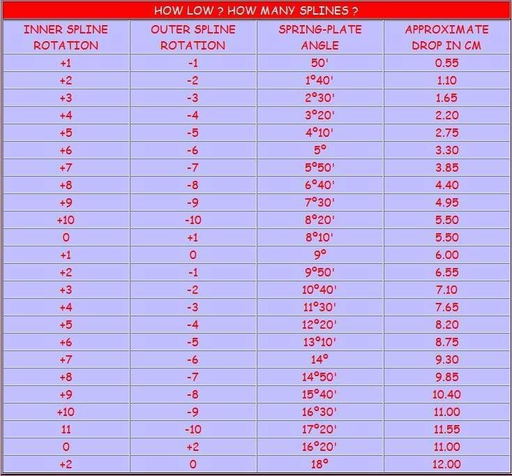
this is for lowering but I suspect that going the other way will work the same. I would loosely set the torsion bar into the splines then add the spring plate. Get a measurment then move the spring plate one notch to see what happens (compare to the chart. Move the torsion up one on the inner spline then measure angle, the drop the spring plate on slpline. If you have a matching pattern you are home free. I was lucky mine went very easy.
Maybe this will help. (I've had this chart so long I don't remember where it came from to give them credit. Sorry to who ever it was as it is a good piece of information)
this is for lowering but I suspect that going the other way will work the same. I would loosely set the torsion bar into the splines then add the spring plate. Get a measurment then move the spring plate one notch to see what happens (compare to the chart. Move the torsion up one on the inner spline then measure angle, the drop the spring plate on slpline. If you have a matching pattern you are home free. I was lucky mine went very easy.
Lee
My opinion is worth slightly less than what you paid for it.
My opinion is worth slightly less than what you paid for it.

-
seabeebuggy
- Posts: 3582
- Joined: Sun Mar 12, 2006 11:25 am
Thank you VERRRRRRRRY much. This will be printed , laminated, framed, spotlighted and recorded in my will.
www.BigMikesGuns.com oe https://www.BMGAA.com
Thomas Jefferson said It may be necessary for a country to have a revolution every 200 years to right the wrongs of a Government.
Got Lead?
Thomas Jefferson said It may be necessary for a country to have a revolution every 200 years to right the wrongs of a Government.
Got Lead?


-
seabeebuggy
- Posts: 3582
- Joined: Sun Mar 12, 2006 11:25 am
I hate to ask but is there a starting point for counting? you go 10+ and 10- you get 8*20' of you were to go past that and go 11+ and 11- does this put you back at 50' like the first one 1+ 1- = 50' ? My thinking is it must go back it cant keep climbing. If so where is the starting point?
Could it be it does not matter? counting 10+ and 10- from any point will be the max?
Could it be it does not matter? counting 10+ and 10- from any point will be the max?
www.BigMikesGuns.com oe https://www.BMGAA.com
Thomas Jefferson said It may be necessary for a country to have a revolution every 200 years to right the wrongs of a Government.
Got Lead?
Thomas Jefferson said It may be necessary for a country to have a revolution every 200 years to right the wrongs of a Government.
Got Lead?
-
Ol'fogasaurus
- Posts: 17881
- Joined: Mon Nov 13, 2006 10:17 pm
It starts where ever you do. It is a clocking puzzle. To start with, you are not dealing with base 100, you are dealing with base 60 (60 degrees in a circle and a degree has 60 minutes)
Down one spline on the inside, up one spline on the outside is equal to 50 minutes. That is give on the first line. For the next setting (the next line down), try breaking one degree into 60 minutes so; two inner splines down and one up, the table says you have 60 minutes (one degree) plus 40 minutes which is 100 minutes. Take the first line's 50 minutes and either add a second 50 minutes and you have 100 minutes or subtract 50 minutes from the 100 minutes and you have 50 minutes. See, simple (well… maybe not!). On the third line it is 2 degrees (120 minutes) and 30 minutes which equal 150 minutes which is the same as 3 50 minute settings/clocking’s (3 X 50 = 150) and it looks like the pattern should continue on this way.
I want to thank you for the nice words and for forcing me sit down and figure it out. I never have bothered with doing it before (it really is too late at night to do this I hope you know. I’ll now have nightmares over it!). If I have helped, it has been a pleasure for me too.
Down one spline on the inside, up one spline on the outside is equal to 50 minutes. That is give on the first line. For the next setting (the next line down), try breaking one degree into 60 minutes so; two inner splines down and one up, the table says you have 60 minutes (one degree) plus 40 minutes which is 100 minutes. Take the first line's 50 minutes and either add a second 50 minutes and you have 100 minutes or subtract 50 minutes from the 100 minutes and you have 50 minutes. See, simple (well… maybe not!). On the third line it is 2 degrees (120 minutes) and 30 minutes which equal 150 minutes which is the same as 3 50 minute settings/clocking’s (3 X 50 = 150) and it looks like the pattern should continue on this way.
I want to thank you for the nice words and for forcing me sit down and figure it out. I never have bothered with doing it before (it really is too late at night to do this I hope you know. I’ll now have nightmares over it!). If I have helped, it has been a pleasure for me too.
Lee
My opinion is worth slightly less than what you paid for it.
My opinion is worth slightly less than what you paid for it.
-
seabeebuggy
- Posts: 3582
- Joined: Sun Mar 12, 2006 11:25 am
 Thank you . All clear now.
www.BigMikesGuns.com oe https://www.BMGAA.com
Thomas Jefferson said It may be necessary for a country to have a revolution every 200 years to right the wrongs of a Government.
Got Lead?
Thomas Jefferson said It may be necessary for a country to have a revolution every 200 years to right the wrongs of a Government.
Got Lead?
-
Ol'fogasaurus
- Posts: 17881
- Joined: Mon Nov 13, 2006 10:17 pm
See, I told you doing math that late at night would give me nightmares. I couldn't sleep so I got out my Baja Bugs & Buggies and looked up what Jeff Hibbard had to say about it:
"There are 40 splines on the inner end of the torsion bar, and 44 splines on the outer end. Turning the inner end of the bar one spline in either direction changes the spring-plate angle 9 degrees 0 minutes. Similarly, turning the spring plate one spline on the bar alters the angle by 8 degrees 10 minutes.... Therefore, it is possible to change the spring-plate angles by multiples of 50 minutes by turning the splines in opposite directions."
That being said, I still go back to the original discussion that you really need the angle finder as your starting point really doesn’t need to be that precise to get to your final angle. Put the torsion bar in, don’t care how it sits in, and mark a horizontal line using the angle finder and a piece of chalk or a sharpie. This is your starting point and can be used as reference. This mark may come in handy if you have to pull the torsion bar out to rotate the bar a spline of two.
Once the bar is firmly, but not completely in place, hold the spring plate at an angle roughly at the angle you think you want. You can do this by using the angle finder to find that angle. Slip the spring plate on the torsion bar and measure the angle of what you have. Now, you can adjust the angles using either or both the chart (for 50 degree adjustments) or the inner spline for 9 degree adjustments or the spring plates for 8 degree 10 minute adjustment. (I think this is what you asked for earlier isn’t it. Silly me!)
"There are 40 splines on the inner end of the torsion bar, and 44 splines on the outer end. Turning the inner end of the bar one spline in either direction changes the spring-plate angle 9 degrees 0 minutes. Similarly, turning the spring plate one spline on the bar alters the angle by 8 degrees 10 minutes.... Therefore, it is possible to change the spring-plate angles by multiples of 50 minutes by turning the splines in opposite directions."
That being said, I still go back to the original discussion that you really need the angle finder as your starting point really doesn’t need to be that precise to get to your final angle. Put the torsion bar in, don’t care how it sits in, and mark a horizontal line using the angle finder and a piece of chalk or a sharpie. This is your starting point and can be used as reference. This mark may come in handy if you have to pull the torsion bar out to rotate the bar a spline of two.
Once the bar is firmly, but not completely in place, hold the spring plate at an angle roughly at the angle you think you want. You can do this by using the angle finder to find that angle. Slip the spring plate on the torsion bar and measure the angle of what you have. Now, you can adjust the angles using either or both the chart (for 50 degree adjustments) or the inner spline for 9 degree adjustments or the spring plates for 8 degree 10 minute adjustment. (I think this is what you asked for earlier isn’t it. Silly me!)
Lee
My opinion is worth slightly less than what you paid for it.
My opinion is worth slightly less than what you paid for it.

-
Ol'fogasaurus
- Posts: 17881
- Joined: Mon Nov 13, 2006 10:17 pm
This is the only picture I could find. I went out to shoot couple of pictures and I couldn’t find where I put my spares torsion bars..

This is a picture of the torsion bar (b\red/brown color) with the outside splines slid onto splines inside the spring plate. You can see the inner splines on the end of the torsion bar that goes into the splines that are located in the middle of the torsion tube.
The number of splines on each end of the torsion bars is different which means the torsion bars cannot be installed backward. Also note, one end of the torsion bar is stamped either L or R on the outboard end of the torsion bar indicating which side of the car each bar goes into. Do not put them in the wrong side as they have taken a “set” and will probably fracture if installed on the wrong side of the car.. Be careful in handling and storing them as if you nick them, the nick can seriously weaken the torsion bar. Rust can also weaken them, the paint on the bar.
This is a picture of the torsion bar (b\red/brown color) with the outside splines slid onto splines inside the spring plate. You can see the inner splines on the end of the torsion bar that goes into the splines that are located in the middle of the torsion tube.
The number of splines on each end of the torsion bars is different which means the torsion bars cannot be installed backward. Also note, one end of the torsion bar is stamped either L or R on the outboard end of the torsion bar indicating which side of the car each bar goes into. Do not put them in the wrong side as they have taken a “set” and will probably fracture if installed on the wrong side of the car.. Be careful in handling and storing them as if you nick them, the nick can seriously weaken the torsion bar. Rust can also weaken them, the paint on the bar.
Lee
My opinion is worth slightly less than what you paid for it.
My opinion is worth slightly less than what you paid for it.
-
rsb
- Posts: 244
- Joined: Fri Nov 07, 2003 6:03 am
Re: Setting preload/rear torsion springs by Lee.
Hey Lee,
I was curious what the chain and trolly jack set up was for? It is the first I have seen or heard of it.
I would assume that it is the quick and easy way to get the trailing arms loaded enough to clear the stop lip, and then the safety/ threaded rod tool is hooked up to keep the arms in place while they are pried out, (chain and jack removed at this point) then the safety tool is used to unload the arms in a controlled fashion.
but you know what they say about assumptions.
Thanks,
Brian
I was curious what the chain and trolly jack set up was for? It is the first I have seen or heard of it.
I would assume that it is the quick and easy way to get the trailing arms loaded enough to clear the stop lip, and then the safety/ threaded rod tool is hooked up to keep the arms in place while they are pried out, (chain and jack removed at this point) then the safety tool is used to unload the arms in a controlled fashion.
but you know what they say about assumptions.
Thanks,
Brian
-
Ol'fogasaurus
- Posts: 17881
- Joined: Mon Nov 13, 2006 10:17 pm
Re: Setting preload/rear torsion springs by Lee.
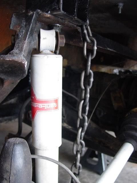
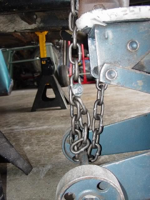
Brian, I think this is what you are talking about. In the older glass buggies they usually put a beam/U-shaped channel across the seating area for some additional support. It is very handy to attach the chain to but the chain can be attached to other places on the torsion tube’s end cap there the shocks are. Just be sure that you are not obstructing the spring plate and access to it.
When you start jacking up the car the car will rise because the torsion bars have nothing to cause them to compress; you jack on the lower shock tower and the car lifts. If you tie a chain to the torsion tube the suspension rises and the torsion bar loads up more. One of the funny things, and I am going to be a “Why-zat” killer here, the car will still rise off the ground as you jack the car up… the front of the trolley will also lift off the ground. I am not completely sure of all the why’s other than the load on the torsion bar gets to the point where it is trying to overcome the loads applied to it but rest assured it does happen and I am still dazzled by it even after doing it so many times.
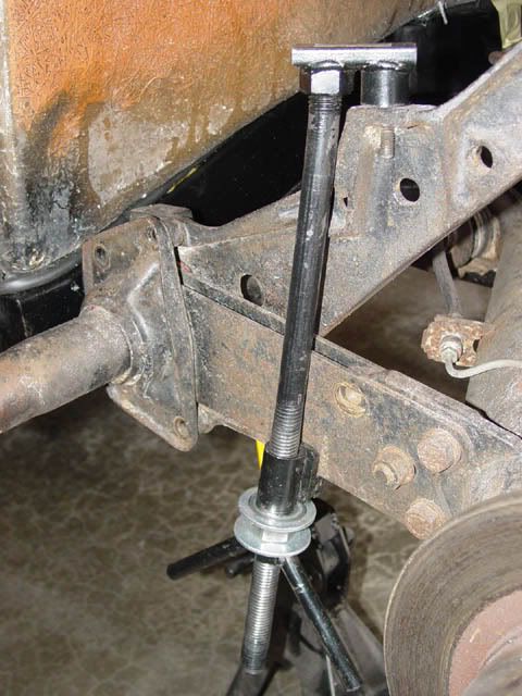
“You will need to insert a bolt in the body mount on the top of the casting. The cup on the end of the safety tool will fit over the bolt head and not slide off that way (we hope). I use a tool designed for changing spring plate but not without modifying it first. I have had a couple of them and I found that adding a couple of washers at the right place keeps them from hanging up. I also add a nut ahead of the wing nut and use the wing nut as a back up/jam nut. When I need to adjust things, I use the nut instead of the wing nut.”
Notice the amount of flex in the long rod part of the “tool”; that shows you just how much load is being applied to the “tool” even though it is in a support configuration. I forgot to mention the need for washers but they are needed.
Lee
-
Steve Arndt
- Posts: 7420
- Joined: Sat Mar 10, 2001 12:01 am
Re: Setting preload/rear torsion springs by Lee.
This seems like a good place to add.
Make sure to trial fit the bushings first. They require a lot of massaging to fit properly if using urethane. The knobs need sanding and extra chamfer so they drop into the housing nice. I had to hone/enlarge the ID so the spring plate fit smoothly. The outer bushing I also had to sand inside and outside to get proper fitment. Lube the piss out of the bushings and splines like Lee said. Also where the splined tube is welded to the spring plate the welds often need dressing. Where they start/stopped the weld there is a raised portion that will hang up on the bushing's inner relief. Trial fitting these parts first will make for smooth travel and easier assembly.
We have a giant plastic mallet from Snap On called the clown hammer. Once I get the extra long bolts started in the cover I release as much jack/chain tension as possible so the arm just barely clears the stop. Some nice taps on the extended spring plate (long bars) help get it started. Then sneak up with the long bolts tightening things down.
Make sure to trial fit the bushings first. They require a lot of massaging to fit properly if using urethane. The knobs need sanding and extra chamfer so they drop into the housing nice. I had to hone/enlarge the ID so the spring plate fit smoothly. The outer bushing I also had to sand inside and outside to get proper fitment. Lube the piss out of the bushings and splines like Lee said. Also where the splined tube is welded to the spring plate the welds often need dressing. Where they start/stopped the weld there is a raised portion that will hang up on the bushing's inner relief. Trial fitting these parts first will make for smooth travel and easier assembly.
We have a giant plastic mallet from Snap On called the clown hammer. Once I get the extra long bolts started in the cover I release as much jack/chain tension as possible so the arm just barely clears the stop. Some nice taps on the extended spring plate (long bars) help get it started. Then sneak up with the long bolts tightening things down.
Steve
My Baja Build
My Baja Build