Posted: Fri Mar 16, 2007 8:47 pm
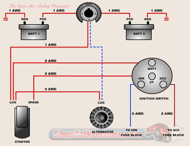
turboblue wrote:Here is a pic to go along with baja5's advice.
The aircooled VW tech forum for Beetles, Buses, Karmann Ghias, and Type 3s. Get engine, carb, electrical, and restoration help from experienced VW owners.
https://shoptalkforums.com/
turboblue wrote:Here is a pic to go along with baja5's advice.
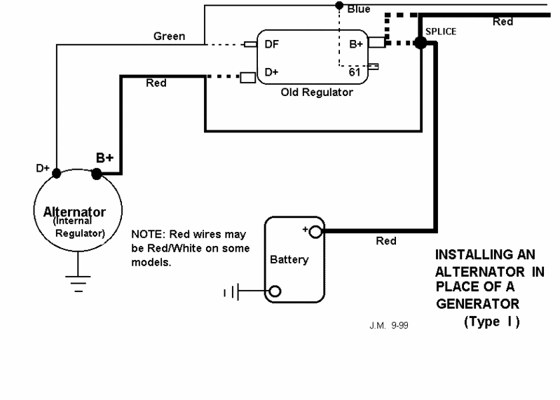
DesertGuy wrote:


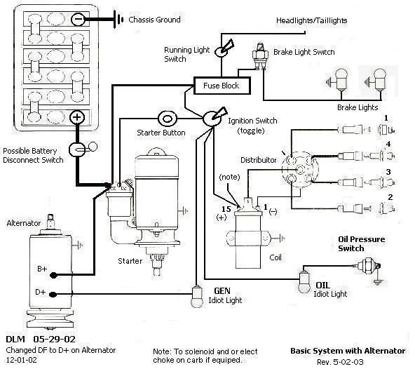

DesertGuy wrote:The Wild Kids wrote: OK So here;s what I have come to decide on. I am going to run a wire from each oil sender, D+ alt to the idiot lights in the dash. Then there will be a wire from the Bat to the power toggle switch to supply power to everything. From Power toggle to IGN toggle momentary switch. From each of the lights will be a jumper wire that will bring power from IGN toggle to the oil and Alt idiot lights. Also there will be another power jumper to the headlight switch for power. From the Light toggle to the lights themselves that will have a "T" in it for power to the tail lights and the other going to the head lights. Then there will be the coil wire from the (+) of the coil to the IGN toggle.
The only ground wire I will have is for the Head/tail lights, brake lights. There will be a power wire for the brakes coming from the main Power toggle. This way only when this switch is (ON) will the brake lights work and anything else for that matter.
I wish I knew of a way that I could draw this out in schematic form for you to be able to visualize what I am trying to describe.
The Wild Kids
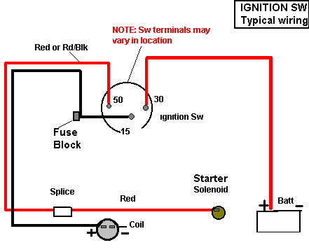
Speedy Jim wrote:The Ignition circuit looks like:
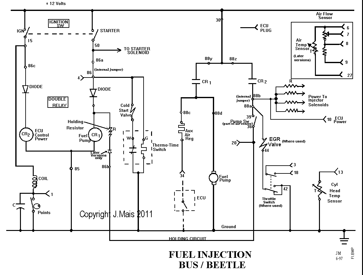
Here is my simplified diagram of the FI system on a Type 1:
Does that cover what you're looking for?