Looking around for the info on rebuilding the centre links and unfortunatly the only info I can find is minus the pictures.
I must confess that this is the bit I missed doing on my front end rebuild last year due to lack of funds, needing the car back on the road and being unable to source a spare. I haven't done too many miles in it yet, the miles I have done have been wobble free, so need to get on and finish what I started before the wobbles return!
I am soon due to take delivery of a complete second-hand spare steering box, tierods, centrelink, idler arm and pitman arm which I intend to overhaul before swapping for the ones fitted to my 412.
I would therefore appreciate any how toos and pics on what to do.
Thanks in advance.
Is it possible to restart a cntrelink rebuild thread?
-
wshawn

- Posts: 209
- Joined: Thu Dec 27, 2007 6:36 am
-
raygreenwood
- Posts: 11907
- Joined: Wed Jan 22, 2003 12:01 am
-
Lahti411
- Posts: 127
- Joined: Sat Jan 29, 2005 2:23 pm
I've rebuilt one centerlink by following the rebuild-thred here, but haven't yet installed it to my car. Rebuild was quite straightforward -only problem was openig the grease cups as i didn't know how thick the material was. I'm still wondering though what kind of bushing i'm supposed to use between the centerlink and the arm that attaches to it. I guess it was supposed to be some kind of a bushing for some drill or something...?
-
Bill K.

- Posts: 563
- Joined: Mon Oct 27, 2003 10:50 pm
I haven't rebuilt one, but I do have info and pictures of the reinforcing bushing on my web site
Slow but sure,
Bill
Slow but sure,
Bill
-
Lahti411
- Posts: 127
- Joined: Sat Jan 29, 2005 2:23 pm
Here's how i opened the centerlink:
I started by filing down the grease cap till i could see what's underneath it

Then i made some slits to the cap with dremel tool

Grase cap finally opened

This is what was left of the cap after i had wiggled it out

Empty cavity

This is what came out of it

And how it was assembled

I made some stainelss steel caps for the rebuild. Material thickness was 1mm if i remember correctly

I made the bushings out of bronze. The dimensions were in my case: outer diameter 25mm and inner 16,1mm. Each cavity needs two bronze bushings and if i remember correctly they were 5 and 6 mm thick. I guess Ray once told these dimensions may vary

Here you can see two centering rings and a snap ring i used to lock the whole package in place. None of the original nylon bushings were used

I should have somewhere pictures of the bronze bushings and final assembly but i couldn't find them now. I'll post them later.
But anyway the bushings only need some slits filed on their facing surfases to allow the grease to flow on to every surface in the cavity. First I had cut the bronze bushings roughly to needed dimension and sanded them with fine sandpaper to final dimension.
I started by filing down the grease cap till i could see what's underneath it
Then i made some slits to the cap with dremel tool
Grase cap finally opened
This is what was left of the cap after i had wiggled it out
Empty cavity
This is what came out of it
And how it was assembled
I made some stainelss steel caps for the rebuild. Material thickness was 1mm if i remember correctly
I made the bushings out of bronze. The dimensions were in my case: outer diameter 25mm and inner 16,1mm. Each cavity needs two bronze bushings and if i remember correctly they were 5 and 6 mm thick. I guess Ray once told these dimensions may vary
Here you can see two centering rings and a snap ring i used to lock the whole package in place. None of the original nylon bushings were used
I should have somewhere pictures of the bronze bushings and final assembly but i couldn't find them now. I'll post them later.
But anyway the bushings only need some slits filed on their facing surfases to allow the grease to flow on to every surface in the cavity. First I had cut the bronze bushings roughly to needed dimension and sanded them with fine sandpaper to final dimension.
-
raygreenwood
- Posts: 11907
- Joined: Wed Jan 22, 2003 12:01 am
-
raygreenwood
- Posts: 11907
- Joined: Wed Jan 22, 2003 12:01 am
You should not need any bronze bushing stock. I did mine with no machine work required to a radial movement tolerance under .003" and axial movement to nil.
There are bushings and bronze washers available through most hardware chains...Jandorf is the common brand. They need minimal work...but tedious work....with a dremel tool for fit. This will take you an afternoon at the workbench.
The stainless cap does not have to be so thick....but those in teh pictures were very nice...this is because it is nothing but a cover. It has no structural purpose.
The cover thickness on mine was .010" stainless. I cut it out with sharp shears...and shaped it with a stack of washers and a socket and mallet...looked just like those just thinner.
In this way, I was able to use a thicker snap ring at the back. I used .030" teflon strip as a radial packing around the washers. The key is also to assemble each pin into the arm (pitman or idler) to measure teh finished depth so you can set the bushing height to about .001-.003" just under that.
Shawn....I can e-mail you those pictures after lunch so you can compare the slight differences. Either way...it yields the same very tight center link.
-
wshawn
- Posts: 209
- Joined: Thu Dec 27, 2007 6:36 am
That would be a great help, thanks Ray.
I've just got to wait a week or two to collect the steering bits and pieces from a generous club member who is collecting the bits from a guy at a VW show that I can't attend in person due to other commitments.
Once I've got my hands on the bits I'll crack on and get it done between looking after the kids, essay writing, work etc.
-
raygreenwood
- Posts: 11907
- Joined: Wed Jan 22, 2003 12:01 am
-
herr_sparky
- Posts: 145
- Joined: Wed Oct 24, 2001 1:01 am
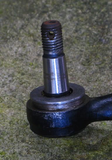
is the purpose of tearing these apart just to replace the nylon bushing? what if there isnt one? i bought a NOS centerlink a while back and theres no nylon to be seen... before i go cutting apart the cap and pull the guts out, i thought i might not need to and just add the missing bushing and be done with it...
-
raygreenwood
- Posts: 11907
- Joined: Wed Jan 22, 2003 12:01 am
No....that picture you posted...shows the outer "urethane" boot missing. What you cannot see....is that the Nylon underneath that boot...that used to cover half of that pin in your picture...was at one time....part of....the nylon bushings INSIDE of the joint. 
So...no only is the the external nylon sleeve gone...but the lateral support it gave to the pin is gone.
look at your picture. Notice how the hole in the steel housing that the pin is coming out of...is larger in diameter than the pin by about .060"?
That nylon used to be a bushing sleeve between housing and pin. It has turned to powder...and fallen off.
The nylon inside....turns to powder as well. 6/6 nylon....was the wrong material. It was defective. 6/6 nylon absorbs water and shatters.
You must get rid of all nylon inside of these joints. Getting an NOS one only delays the inevitable....and spends money.
This really is only a few hours of work and cheap money...for a centerlink that will then be fully rebuildable....and a major steering and track control improvement.
Every type 4...I have ever seen...has this problem...because of the nylon used.
Using bronze bushing stock and machien work is very nice...but is totally unnessary. I used simple bronze thrust washers available at any hardware store. Stack them up, size the OD and ID with a dremel tool....grind grease slots in them...and they make a very tight joint with no play. I can send you pictures if I have not already. Ray
-
herr_sparky
- Posts: 145
- Joined: Wed Oct 24, 2001 1:01 am
-
raygreenwood
- Posts: 11907
- Joined: Wed Jan 22, 2003 12:01 am
If you take a look at Lahti411's pictures above....the picture #7 from the top.....see the nylon bushing that is closest to the threaded end? Yours only has the lower flange left...and is missing all of the upper section.
What starts the damage (other than nylon just turning to mush...no kidding!) ....is a combination of misalignments to the centerlink...that cause lateral pressure to that bushing that protrudes thr ough the top and covers each pin. These misalignments are first caused by the overly soft bonded rubber idler arm bushing and stiff or rusted tie-rod ends.
Poor wheel alignment or worn struts also increase the flexing angle of the tie-rods. This puts more vertical loads on the center link. As the nylon starts turning to mush....the lateral movement of the rotating pins in the centerlink increases....tearing up the nylon even faster and allowing more water leakage.
Putting a solid bronze or brass idler arm bushing in at the same time as you rebuild the center link is a HUGE improvement to handling and steering. Ray