aha, that sounds very interesting! so perhaps this would work:
get a T4 crank with T1 rod journals
flip one T1 connecting rod for each cylinder bank (3mm offset flipped = 6mm total change from center, right?)
make adapter plates to match the new bore spacing, which would be equal to 911 (one bore would remain in the same spot, the other would move in 6mm).
bolt up 911 heads and cam towers w/o modification (other than removing unused tower).
this sounds great and totally doable, which makes me think I'm probably missing something, but I'm encouraged. I think this could be a really fun project.
thanks for the additional feedback guys,
dave
911 heads
-
Frallan

- Posts: 667
- Joined: Sun Mar 30, 2003 12:01 am
Check carefully on Russ Collins camtowers. He only plugged the holes were the head would have been on a 911.
In this way you save the "hassle" to manufacture camshaft bearing extensions like we did.
I think mine look cool but it is an unnecessary extra item.
If you then manage to copy his way of cutting and indexing an original cam, there you go and save a lot of money and question marks.
I really would like to hear how it was done practically and even better, see pictures.
If someone told he would do it, I would just say "good luck" and give him 0 or little chance to work BUT Russ did it and he proved it by not only racing but also driving a lot on the street, for years.
So, it seems to be feasible.
Bobtail, you couldn´t pull some strings and get more details?
-
Type 4 Unleashed

- Moderator
- Posts: 2202
- Joined: Tue Nov 08, 2005 10:43 pm
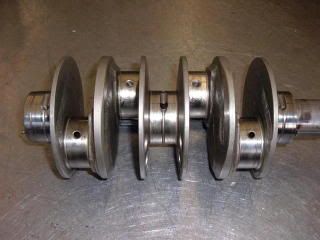
Here is an issue that should be looked at, when they weld up a Type 4 jrl crank which has a jrl width of about 1.020" then
cut it it for the Type 1 width of about .890", in the picture of this crank that this was done, the jrls may be already offset some possibly around 3mm each.
The sides were the weld was left to take of the jrl width is opposite the mains which feed the rod jrls, and to keep the oil hole centered in the rod bearing
Richard
EMW
“Have you ever noticed how some people never
have the money to do it right, but can always
find the money to do it twice ?”
EMW
“Have you ever noticed how some people never
have the money to do it right, but can always
find the money to do it twice ?”
-
M-Owen
- Posts: 64
- Joined: Wed Dec 05, 2007 5:23 pm
Frallen I was thinking the same thing, Dave I am currently work a simular Idea I am using plates ( thickness undetermined as of yet ) with the 118 bore spacing. I am however thinking it would be better to offset the small end by 3mm on type 4 66mm rods. I was a little worried about welding the crank and the difference in length of the Type 1 rod is 10mm over the 1.8 rod. Since I plan on using stock 911 pistons and cylinders I am assuming that the rod lenth will matter.
-
M-Owen
- Posts: 64
- Joined: Wed Dec 05, 2007 5:23 pm
Who completed the work on the crankshaft shown in the picture? One of the problems here is trying to get a machine shop to understand what you are asking them for. The more I read these last few posts the more it's making sense.Type 4 Unleashed wrote:Here is an issue that should be looked at, when they weld up a Type 4 jrl crank which has a jrl width of about 1.020" then
cut it it for the Type 1 width of about .890", in the picture of this crank that this was done, the jrls may be already offset some possibly around 3mm each.
The sides were the weld was left to take of the jrl width is opposite the mains which feed the rod jrls, and to keep the oil hole centered in the rod bearing
-
Type 4 Unleashed
- Moderator
- Posts: 2202
- Joined: Tue Nov 08, 2005 10:43 pm
This crank was done over 15 years or more ago, and more than likely was done in Germany, but no markings to say by who.
There are machine shops, then there are machine shops that all they do are cranks, and would have a better understanding of what you want.
One thing you have to consider is the stroke (66mm) & rod (5.0") which gives a rod to stroke ratio of 1.92 to 1. I don't remember the pin heigth of a 1.7 or 1.8 piston but that needs to be compared to the 6 pistons you are planning to use. and any rod length over 5.160" will give well over 2.0 to 1 rod to stroke ratio.
The problem I am getting at, is the thickness ? of the plate that you want to use to use the 6 cyl's bore spacing, it will have to be thick enough to be able to screw cyl studs into, and your rods will be too short, to be able to get any deck heigth.
Richard
EMW
“Have you ever noticed how some people never
have the money to do it right, but can always
find the money to do it twice ?”
EMW
“Have you ever noticed how some people never
have the money to do it right, but can always
find the money to do it twice ?”
-
M-Owen
- Posts: 64
- Joined: Wed Dec 05, 2007 5:23 pm
I found a shop called Demello Crankshaft, I spoke to the owner and he seems very knowledgeable about the subject and can counterweight the crankshaft as well. I would welcome any feedback about this shop if anyone has used them. AS far as the rod length is concerned, I was thinking that the deck height could be milled accordingly I would like to try and use the type 1 rod as was suggested in an earlier thread. I do admit there will be a little math involved, I will post my findings as soon as I can
-
Piledriver

- Moderator
- Posts: 22760
- Joined: Sat Feb 16, 2002 12:01 am
Interesting finding...The aftermarket T1 Hbeam rods aren't offset, which kinda makes me wonder if a little offset really matters...
(The stock one are offset, as are the CB Ibeams I have at least)
DPR and Demello are the only places to go for the crank.
google dpr machine...
Jake swears by DPR, if you buy one through the Type4store it's a DPR with Jakes specs.
(The stock one are offset, as are the CB Ibeams I have at least)
DPR and Demello are the only places to go for the crank.
google dpr machine...
Jake swears by DPR, if you buy one through the Type4store it's a DPR with Jakes specs.
Addendum to Newtons first law:
zero vehicles on jackstands, square gets a fresh 090 and 1911, cabby gets a blower.
EZ3.6 Vanagon after that.(mounted, needs everything finished) then Creamsicle.
zero vehicles on jackstands, square gets a fresh 090 and 1911, cabby gets a blower.
EZ3.6 Vanagon after that.(mounted, needs everything finished) then Creamsicle.

