911 heads
-
Frallan

- Posts: 667
- Joined: Sun Mar 30, 2003 12:01 am
The founder of the company I work for has a good quote that is so true
"To do what nobody else has done before, is actually quite difficult".
Now the fact is that I/we did not do this as first timers.
We copied what had been done in Swedish (and probably Germany too) Rallycross for some years, even if if it was way back in 1977.
Wally, the ring is steel and yes it came on when the car was turbocharged.
They are slightly shrunk fit and no, the cylinder was never honed afterwards. In fact the piston is not that high when running 7:1 compression.
NO, the cylinders are not moved in relation to original spacing.
In fact the studs are even in steel inserts in the block. They just go right through the steel plates.
The only offset are the heads over the cylinders.
The only tricky problem, is that one of the through bolts hits right in to the main oil channel and that has to be sealed by o-rings in the inner part of the block and with further o-rings between the plate and the block.
As I will take the engine apart during spring and clean it all up, I could take some pictures, but not now.
Thanks for all the comments.
I repeat though that this is not the way it should be done today.
Russ Fellows TIV is a much better soultion and should be seen as the way forward.
It would be nice to see how the cam was indexed and pinned together and then get it to work reliably.
Bobtail, any chance in the future to get description and pictures?
Last edited by Frallan on Sun Dec 30, 2007 3:01 pm, edited 1 time in total.
-
Frallan
- Posts: 667
- Joined: Sun Mar 30, 2003 12:01 am
Sorry for another T1 but what about this one way back from 1975?
Ford BDA 4 valve heads and homebuilt everything else.
Just check the crank and rods plus own castings for the chain camdrive.
It runs intermediate belts and then chains to the camhafts.
Now the main point that you might miss if you do not know what to look for is the top of the engine case.
It has been lifted and steel inserts for the main bearing saddles lined together with the steel side plates......any comments about that one?
I heard this engine naturally aspirated with Lucas timed mecahnical injection on 10 000 rpms in 1977, Did I love it? Absolutely lovely.
BUT, Jake sit down, it is converted and watercooled.
Last edited by Frallan on Sun Dec 30, 2007 2:44 pm, edited 1 time in total.
-
dstar5000

- Posts: 4555
- Joined: Tue Feb 12, 2002 12:01 am
JEEZ! LOOK at those counterweights, not even knife-edged!
and it went to 10K RPMS?
SCARY!
I would have LOVED to heard that engine scream!
Don
"Let me say it as simply as I can: transparency and the rule of law will be the touchstones
of this presidency,".. Barack Obama January 21, 2009, 30 minutes before he signed the law
sealing all his personal information....
of this presidency,".. Barack Obama January 21, 2009, 30 minutes before he signed the law
sealing all his personal information....
-
Frallan
- Posts: 667
- Joined: Sun Mar 30, 2003 12:01 am
Well I do not know how scary it is. The crank (and rods) were hunked out of a steel called SIS 2541 and like written before way back many years.
It has survived endless races and it is still around, so it should not be that bad.
Also I note that there are no counterweights in normal way, it is a full circle crank. I do not know the theory why people do that (I never fancied full circle as I think it is just a labor saving way to design a crank, not better) but my thought about your comment is that the "counterweights" as mentiond by you Don can not whip anything around as they are fully round, i.e. no need to knifeedge.
See what I mean?
Another engine like this was made few years later in Sweden and is also still alive but used Saab 4 valve heads.
What I do know that characteristics on them is that they were very heavy with the homemade water and camcovers plus much heavier heads.
-
M-Owen
- Posts: 64
- Joined: Wed Dec 05, 2007 5:23 pm
Do you think it would be a good idea to used steel plates for the spigot openings on the type 4? I was thinking by using two 12mm steel plates and milling the spigot mounting down 12mm I could use my 3.2 heads and cylinders by just placing the 86mm stud spacing on the steel plates . I will try to illustrate what my plates might look like and post
-
70dragbug
- Posts: 534
- Joined: Sun Oct 27, 2002 1:01 am
I love stuff like this!! Hey Frallan if you have any info/pics on things like that I´m always interested! I´ll give you my personal e-mail if you like. I´m also the person who sent you a pm in Jake´s forum on the steel plates..Another engine like this was made few years later in Sweden and is also still alive but used Saab 4 valve heads.
-
dstar5000
- Posts: 4555
- Joined: Tue Feb 12, 2002 12:01 am
Yes Frallan, you are correct. I mis-spoke.
It is indeed a *full-circle* crank and must weigh a TON!

At least we know they will last a long time, eh?

Don
It is indeed a *full-circle* crank and must weigh a TON!
At least we know they will last a long time, eh?
Don
"Let me say it as simply as I can: transparency and the rule of law will be the touchstones
of this presidency,".. Barack Obama January 21, 2009, 30 minutes before he signed the law
sealing all his personal information....
of this presidency,".. Barack Obama January 21, 2009, 30 minutes before he signed the law
sealing all his personal information....
-
M-Owen
- Posts: 64
- Joined: Wed Dec 05, 2007 5:23 pm
I was wondering if you offset the small end of the connecting rod 3mm from center to compensate for the differance in Bore Centers Porsche 911 = 118 mm VW Type 4 = 124 the differance being 6mm if each piston pin land was machined 3mm on one side and a 3mm spacer on the other , steel plates were used to mount the barrels at a 118mm bore center you could just cut one cylinder from the cam towers and the cams would be easier to make work.
Does any body know if you can run a piston in a cylinder with the rod offset in the bore?
Your thoughts on this idea would be apprieciated
Does any body know if you can run a piston in a cylinder with the rod offset in the bore?
Your thoughts on this idea would be apprieciated
-
Piledriver

- Moderator
- Posts: 22760
- Joined: Sat Feb 16, 2002 12:01 am
Don't know, but the T1 rod big end is offset some amount (why they have an "up") imagine one could do the same on a T4, usually get welded cranks w/T1 rods anyway.
Having a custom offset put in might be NBD, perhaps some from the rods as well, the bearings are typically much narrower than the rods.
Example--- The Supra 2JZ rods are >~T4 width/55mm journal. (WWRRRRRRRRONG---52mm journal. Bummer.)
It wouldn't surprise me if you could narrow those to T1 width and get quite a bit... Can't recall T1 width, *.866?) but the 2JZ rod is 1.022" BE.
Double checking that the BE is 55mm... Something isn't jibing, just registered that it might be smaller, BE is only 2.165, indicating a ~52mm-ish pin dia. (Could be a feature..)
Addendum to Newtons first law:
zero vehicles on jackstands, square gets a fresh 090 and 1911, cabby gets a blower.
EZ3.6 Vanagon after that.(mounted, needs everything finished) then Creamsicle.
zero vehicles on jackstands, square gets a fresh 090 and 1911, cabby gets a blower.
EZ3.6 Vanagon after that.(mounted, needs everything finished) then Creamsicle.
-
Type 4 Unleashed

- Moderator
- Posts: 2202
- Joined: Tue Nov 08, 2005 10:43 pm
Why offset the small end of the rods ?
If this is done on a Type 4, which has a wider bore spacing than a type 1, when the center cyl is cut out of the cam towers then welded back together, why not match them to the bore spacing of the engine their intended for, same with the cams ? I don't know, maybe I am missing something here.
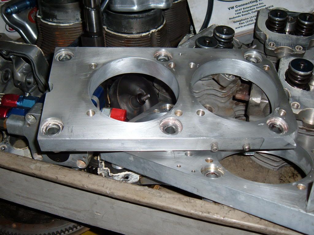
Here's a pic of a plate used to mount Scat Split Ports, which I think have fairly close stud spacing to the 911 ? The Plate is Aluminum, I think Aircraft grade 6061 ? The cyl spigots on these plates are for 105mm Type 4 cyl's.
If this is done on a Type 4, which has a wider bore spacing than a type 1, when the center cyl is cut out of the cam towers then welded back together, why not match them to the bore spacing of the engine their intended for, same with the cams ? I don't know, maybe I am missing something here.
Here's a pic of a plate used to mount Scat Split Ports, which I think have fairly close stud spacing to the 911 ? The Plate is Aluminum, I think Aircraft grade 6061 ? The cyl spigots on these plates are for 105mm Type 4 cyl's.
Richard
EMW
“Have you ever noticed how some people never
have the money to do it right, but can always
find the money to do it twice ?”
EMW
“Have you ever noticed how some people never
have the money to do it right, but can always
find the money to do it twice ?”
-
Type 4 Unleashed
- Moderator
- Posts: 2202
- Joined: Tue Nov 08, 2005 10:43 pm
Frallan, do you know what the stroke on this crank was ?Frallan wrote:Sorry for another T1 but what about this one way back from 1975?
Ford BDA 4 valve heads and homebuilt everything else.
Just check the crank and rods plus own castings for the chain camdrive.
It runs intermediate belts and then chains to the camhafts.
Now the main point that you might miss if you do not know what to look for is the top of the engine case.
It has been lifted and steel inserts for the main bearing saddles lined together with the steel side plates......any comments about that one?
I heard this engine naturally aspirated with Lucas timed mecahnical injection on 10 000 rpms in 1977, Did I love it? Absolutely lovely.
BUT, Jake sit down, it is converted and watercooled.
And no one has commented on the rod bolts being backwards...
Richard
EMW
“Have you ever noticed how some people never
have the money to do it right, but can always
find the money to do it twice ?”
EMW
“Have you ever noticed how some people never
have the money to do it right, but can always
find the money to do it twice ?”
-
Type 4 Unleashed
- Moderator
- Posts: 2202
- Joined: Tue Nov 08, 2005 10:43 pm
Don, how about a 1628cc Type 4 that turns 14,000 rpm.dstar5000 wrote:
JEEZ! LOOK at those counterweights, not even knife-edged!
and it went to 10K RPMS?
SCARY!
I would have LOVED to heard that engine scream!

Don
A Bonneville Salt Flats Class Motor, 105mm x 47mm...
Richard
EMW
“Have you ever noticed how some people never
have the money to do it right, but can always
find the money to do it twice ?”
EMW
“Have you ever noticed how some people never
have the money to do it right, but can always
find the money to do it twice ?”
-
M-Owen
- Posts: 64
- Joined: Wed Dec 05, 2007 5:23 pm
Hey Don,
I may not be conveying the idea I am having correctly, The reason I am doing this is because I am trying to avoid the cutting and realignment issues with the cam towers and cams. I will also admit that this is just an experiment only because I have so many extra parts laying around.
I must say however that those plates are impressive. When there are used do you mill the case to compensate for their thickness? If so do you have pictures of the Case? The engine?