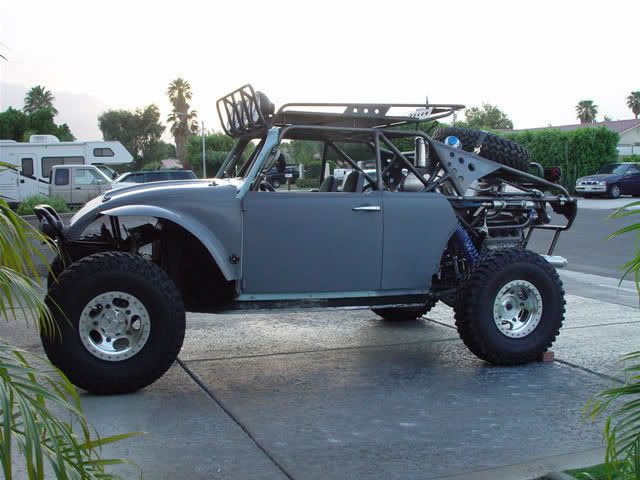
Finally... the time has come that I can start on the wiring of the baja bug. The baja will have many functions that are found in a street vehicle with the addition of off road components.
My intent on this wiring project is to "over-engineer" the system. Too many times I have seen cars wired to the bare minimum... only to be left "tapping" in here and there for an additional circuit. I am planning to intentionally leave "blank" circuits for later use, if needed.
I am going to break this down into manageable sections or harnesses, at least that is my hope. I have broken the areas into the following: (Please keep in mind that this is from scratch, so to speak. I am going to try to wire it without pre-made circuitry)
Charging/Ignition/Start
Engine Computer
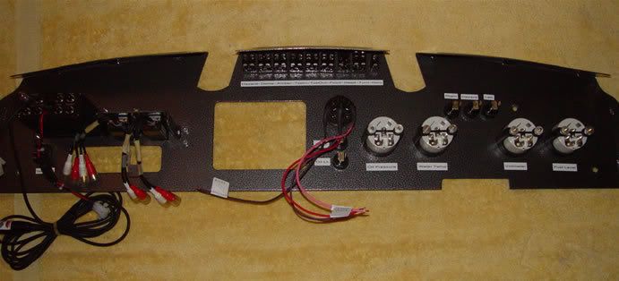
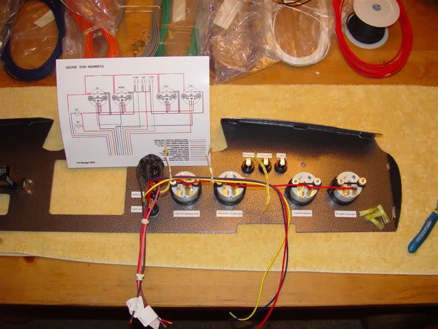
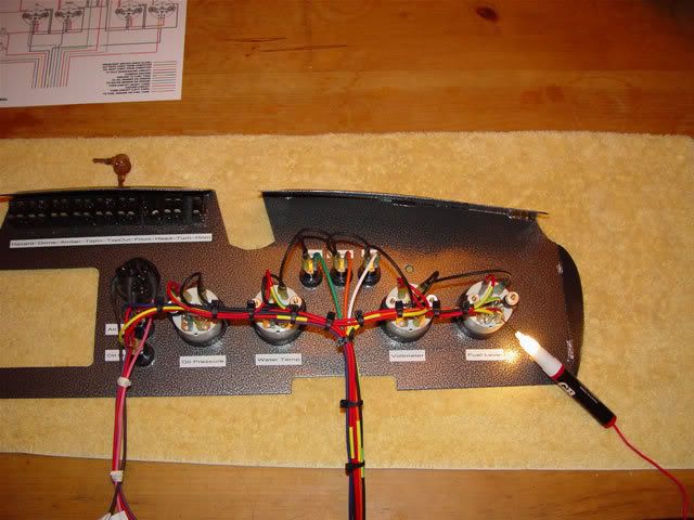
Dash Components
Ancillary Components
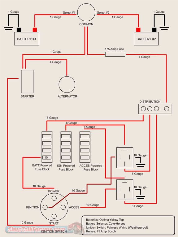
With that being said, my first thought is to wire the Charging/Ignition/Start circuit and put power to the various fuse blocks that I need.
I will be posting the various schematics, diagrams, whatever... so if anyone sees any problems... please let me know. My order from DelCity should be arriving soon... (Unfortunately, they take forever)