What might be a way to go for you is to get a short three or four foot harness out of the ECU and connect those wires to some terminal strips that will always be connected. Then you can either make or buy a harness with the correct sensor and injector connectors on one end and nothing on the other. Get them in 8 ft or 12 ft lengths and once installed and routed you can cut to length and connect to the matching terminal for easy tracing and adding and removing.
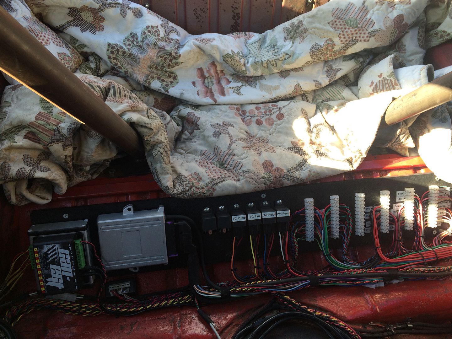
Mario has a good example of how his Harness is made in the back of his Bug.......It's a lot more wiring than any of us have or need but then he is the test and tuner for all his stuff also.
He has some great ideas in wiring since he is pretty well a Professional in the trade with all his work experience and knows all the cool stuff to use.
Take a look at other wiring harnesses and use the parts that work for you and ignore the parts you don't like.
There are many ways to accomplish the same thing.....what works for me might not work for you but you could easily modify it to fit your needs.
This is USA supply but I'm sure you could find something like this in your area....
https://www.amazon.com/electrical-termi ... l%20blocks
https://www.wiringproducts.com/power-di ... ion-blocks
I used the first and second images shown in my build but you might want to use something else that would work better for you.
Just spend a little time planning it out and leave room for expansion.....you know you will add other things as you go.
Here is a pic of Mario's back seat....hopefully he won't mind if I post it.

I found through the years that what was good one year could be improved the next year or simplified the year after.
I have rewired my buggy almost every time I pull it down for the winter. I find something I can do better....or simpler or cleaner.
Start collecting wire colors.....you will need them.
I can't say enough good about Mario's harness....It is color coded to his standard and all his harnesses are wired the same color wise for ease of troubleshooting and connecting. You even get a printed color sheet with all the wire colors marked for installation. It really makes it almost plug and play.
Any issue I usually had on startup was hooking up a wire on the relay to the wrong terminal. Rechecking the colors according to my pictures or to his sheet fixed the non start issue.
Note that he has each line in its own sleeve so you can keep track of which run is which. All ground wires are black so you have to hook those in the right connection too.
The PLX will have an Analog (Gray) wire that can be hooked to the correct ECU input terminal for logging and Autotune.