ts39136 wrote:Great paint work and color choice. Once it's toned down with a little dust it will look perfect!! Awesome metal work, too. Gives me something to aspire to.
Still hard to see how that is going to be able to pivot. Voodoo or something I guess, looks like it is built for strictly up and down movement, not any angle to be put on it.
Just went out in the garage to get some better pictures on how the shock pivots. I made the mounts at an angle so it had enough room to pivot forward when the arm comes up. To pivot backward it has about an inch or so play but as you can see that the shock wont be doing that (shouldnt anyways ). So when the arm comes up it will pivote the shock forward, not by much so I have plenty of room. I'm working on a dash mockup right now too.
Here is the dash layout I came up with. The steering wheel has a button in the middle for a horn I wanted to wire that up along with having the passanger also have a button on like the grab handle. Not positive how I would wire this, maybe power to both on same circuit and have them grounded on the same circuit? Pressing both at once wouldnt cause any problems? Anyways here is the layout.
If it was my choice I would put the GPS closer to you, you will at times want to see it, less time looking at or for it will be more time spent on the road ahead.
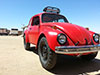
This is awesome. I just stumbled upon this thread and I'm looking at your avatar thinking man that blue bug looks familiar...
I'm one of the AZ guys http://www.pepeazul.com
Nice build you've got going here and nice job on Pepe. We changed a few things Most notably, we added the Bilstein cheater shocks on the back and Greg had an awesome transmission built for it. Anyhow, keep up the good work!
Chris
ccoleman wrote:This is awesome. I just stumbled upon this thread and I'm looking at your avatar thinking man that blue bug looks familiar...
I'm one of the AZ guys http://www.pepeazul.com
Nice build you've got going here and nice job on Pepe. We changed a few things Most notably, we added the Bilstein cheater shocks on the back and Greg had an awesome transmission built for it. Anyhow, keep up the good work!
Chris
Thanks, I've been following the site. Been waiting for your Baja 500 report, just read it. Congrats on making it halfway, what an experience that must have been. Always surprises me what class 11's can go through. I'd be interested in seeing the updates you've done to the car. Oh and I probably should update my avatar, lol.
jps1145 wrote:I would suggest an oil temp guage also, maybe a cylinder head temp guage too.
I messed up on the diagram, the gauge is a oil temp. Been researching the cylinder temp but people are saying sometimes theres spark plug sealing issues, and accuracy issues. I think running good oil with the full flow setup, fan on the oil cooler, temp gauge to keep an eye on it should work out ok. Here is an updated dash diagram. GPS will come later I can probably mount it on the grab handle somehow in front of the breakers. Need to start creating wiring diagrams.
With engine monitoring " more is better" but with that said I have been running an oil temp with sensor at the drain for years running a turbo with no problems. One thing that will save you if you loose oil while running and help with longevity is running a good oil.
Ok I have been getting together what I am going to do with the wiring. My buddy gave me an EZ Wiring harness he ended up not using. So I have all the wiring in different colors and it is even labeled on the wiring what it is for.
So here is a breakdown of all the circuits I am going to have.
Gauge Circuit
Breaker Amps: 5
AWG: 16
Power Source: Ignition
Switched: No
Relay: No
Includes: Oil temperature gauge, oil pressure light, oil pressure light.
Running Light Circuit
Breaker Amps: 5
AWG: 16
Power Source: Ignition
Switched: Yes
Relay: No
Brake Light Circuit
Breaker Amps: 5
AWG: 16
Power Source: Hot
Switched: No
Relay: No
GPS Circuit
Breaker Amps: TBD
AWG: 14
Power Source: Ignition
Switched: No
Relay: No
I am not sure on some of the breaker amp sizes. Some of my components are 6.8 amps or 8.2 amps so a 10 amp breaker would be the most obvious choice right? Also should I put a main breaker between the battery and the cutoff switch? I made up a diagram of the idiot light wiring. Any input is appreciated.
I like how you organized your circuits by type/switching/etc.
One suggestion... put the GPS to "hot" instead of "ignition". It's a low amp draw and be left on for hours, but most gps's have a warm up time. You wouldn't want to wait for it to warm up/aquire signal once you get going (for example from an engine off pit stop).
I would size breakers by wire size and not load.
It looks like the air pump will be the only device with a significant start up load to figure in.
Don’t ever yield your gift of dream; Your knack for gumption, too. For “It’s the crazy ones that have all the fun," if dreamers yearn to do.
Ok let me see if I understand this correctly. So this site: http://www.bdbatteries.com/wirerules.php, it shows a table of the maximum amps for that wire size. And has the calculator for voltage drop. So lets take the headlight circuit for example.
The headlights will be the H4's and they will be about 60 watts each. That is about 4.5 amps give or take each, so 9 amps for both. I just looked the harness over and it has the headlight power wires that are 14awg. According to that website the maximum amps for the 14awg wire is 25. And since the length of the wire will be probably less then a foot going to the relay it will have less than a 1% voltage drop. Now from the relay could I use the 16awg the harness has going to the headlights themselves? 16awg max amps would be 15 and at 3 feet to the headlights would have a voltage drop of 2%+ according to the website. So the breaker size I would want to put on this circuit would be 15 since thats the most the 16awg could handle? Do I have this right?
Max Amps
14 AWG: 25 16 AWG: 15
Headlight amps: 9
14 AWG to 15 Amp breaker > 14 AWG from breaker to relay > 16 AWG from relay to headlights
Those... "kits"... don't read minds nor do they normally understand what a true car "abuser" can/will do so they don't normally plan for what is/can be done nor allow for voltage drop on big draws over long distances.
Hint: remember (for off-road anyway), within the rules (of electricity in this case) there are many legitimate options and "the right way" is not always the right way... think about it.