An engine run cart build

Offroad VW based vehicles have problems/insights all their own. Not to mention the knowledge gained in VW durability.
Ol'fogasaurus
Posts: 17881
Joined: Mon Nov 13, 2006 10:17 pm

Re: An engine run cart build

Post by Ol'fogasaurus »

"My stand is clamped to the cart as the intention was to make it removable in case I needed the cart for something else.
As of today, it's never been removed............ :mrgreen: "

Your statement about changing the oil is one of the reasons (along with watching the shows on Spike where they use the dyno) I am building some of the accessories and have made the center of the crankshaft where I am planning on putting it. I plan seeing if I can form a sheet of flat stock onto a pan with a drain at the bottom with a hose going straight into a gas can for recycle. :wink: Silly but while I could do it another way, this way eliminates the number of chances I have to handle a liquid.

Your working end of the cart is why I chose the longer wheel base to start with; the tool/working shelf which is another add-on I am planning on doing.

Yours, DaleM, a Mr. Hilton, Alan Freilich and the rest (not to forget anyone so I am using "and the rest") who have posted here and on Dale's site have heavily influenced the direction I have taken in this; still looking for more input if someone has one or many.

Lee
Ol'fogasaurus
Posts: 17881
Joined: Mon Nov 13, 2006 10:17 pm

Re: An engine run cart build

Post by Ol'fogasaurus »

After much thought, I decided to go with my second idea as it just isn’t worth it going the way I started then having to re-do it.

Image

I started laying out what cuts I am going to have to make to the ¼” plate; I started out by laying out the shape of the bell housing as that and the fasteners locations are going to have a lot to do with the shape of things to come. The starter I left alone for a while as that is the bugger in the whole thing.

I started by using some old 2” masking tape I had laying around (I need to lay one more course on the left but it will be done later today after I get feeling back in my fingers) and covered over the work area; I left some overlap in case I wanted to pull the whole thing off as a template. Using the flat end of a ballpeen hammer I tapped the ends of the tape to neaten it up for the photos (which may have been a mistake); I then found each of the holes and using the ball end of the hammer, put it in the hole and using another hammer I tapped it to cut the tape. I still had to do some clean-up but after I cut, I stuck the end of the Sharpie marker I was using up in the hole and the removed hole stuck to it and I pulled it out. For those who didn’t know, this is the way they used to make gaskets to fit.

Image

I then taped the sides of the bell housing so that I didn’t get ink all over it then bolted it is place finger tight and drew around the edges with a fine point Sharpie (the one I was talking about ^, they are a bit smaller in diameter than the regular pointed Sharpie).

Image

This will give me a starting point for where to make the cuts on the plate and to build the “tower” for the cart.

Lee
Ol'fogasaurus
Posts: 17881
Joined: Mon Nov 13, 2006 10:17 pm

Re: An engine run cart build

Post by Ol'fogasaurus »

Image

This is about where I am right now. I don’t like it as it short cuts some of the support I would like to give the plate; this is about what I showed on the last sketch only it would be a 1” X 2”rectangular tube rather than the 1” angle iron shown. I would also like to see just how tight of a radius bend I can make with the 1 X 2 tube with a welded 90° joint being another, but not as good, option (I don’t think I want to do it using kerfs but the option is still there).

The view at the bottom is what I was originally planning but I think that is gone as an option now. I think the mounting plate will have to be welded to the stand on the outside of the support now, not sitting inside like I wanted. As a second option to where I am going would have been to weld the plate to the inside for support incase my welds did not hold (I don’t think that would happen but I still don’t trust my welds… yet) but it will have to be on the outside due to the starter mounting location and direction.

Lee
Ol'fogasaurus
Posts: 17881
Joined: Mon Nov 13, 2006 10:17 pm

Re: An engine run cart build

Post by Ol'fogasaurus »

Image

This is where I am now; the center of the crankshaft is where the circle is and I was planning on making it to be 30" off the floor. After going out and measuring, 30 inches way too short even when sitting on a short stool. My work bench is about 34" off the floor and is closer to feeling better but still a bit too low. It works OK when sitting but still feels a bit low (I do not have an engine to compare things to so I am pretty much guessing here). 36" feels better when standing and is still workable when sitting.

My cart as is sits now, has the top of t he rails 6 3/4" off the deck, a width between the centerline of tires and rails of 23" and a length of 50" so I think it should be stable at 36"s.

Any comments or ideas pertaining to the height of the crankshaft centerline before I start cutting metal again?

Lee
User avatar
bajaherbie
Posts: 9967
Joined: Sat Jul 15, 2006 7:07 pm

Re: An engine run cart build

Post by bajaherbie »

35 9/16"
Of all the paths you take in life, make sure a few of them are dirt.
Ol'fogasaurus
Posts: 17881
Joined: Mon Nov 13, 2006 10:17 pm

Re: An engine run cart build

Post by Ol'fogasaurus »

Image

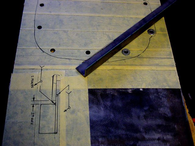
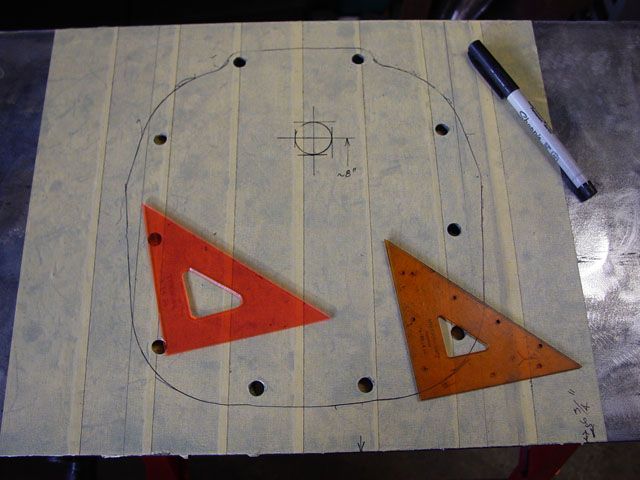
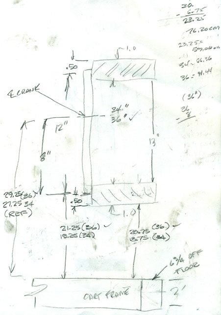
Last night, while thinking things over I made a cut sheet/drawing. It sure speeded things up.

Image

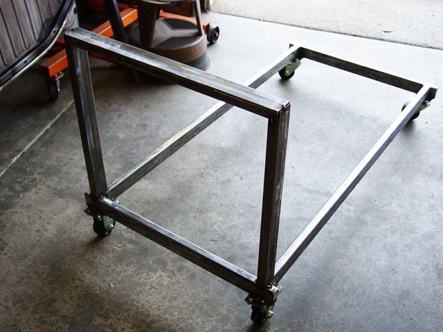
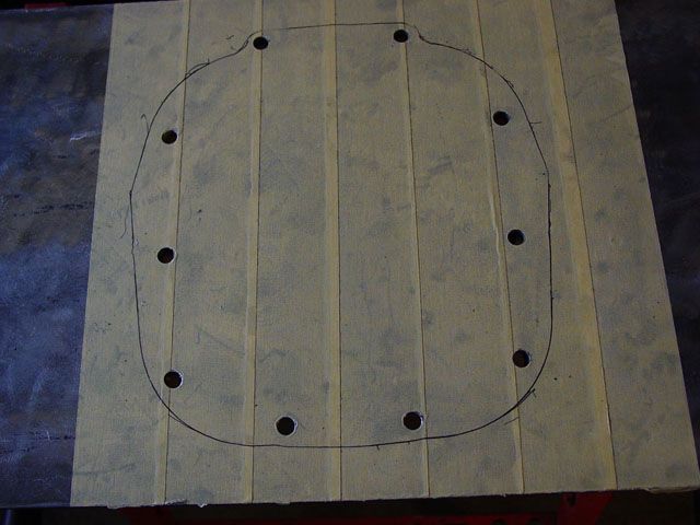
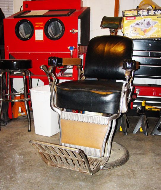
This is looking at the cart where the bell housing is going to be located. I am a quarter of an inch higher than I planned on being; I still can’t read a tape measure it seems.

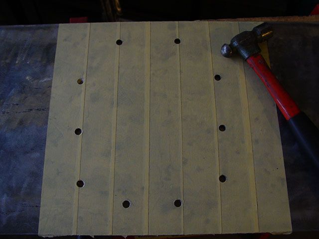
I laid both of the lengths of material side by side, clamped them together and squared the ends together. I then, while still clamped together, I measured the cut I wanted but 7/8 of an inch longer than needed; my measurement, if you look at the cut sheet was to the bottom of the 1 X 2.

The extra ¾” was for the end cap which is in the last picture.

Image

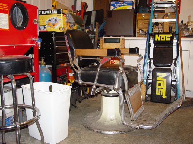
This just shows the cart from the other end (obviously). Making sure that everything was vertical front to rear and side to side was a comedy of… well, not too many errors; I had straight edges, and more clamps and clinches than in a tag team professional ‘rasslin’ match. I had to have stops to make sure that the rear of the tube was in line both to the rear and the side of the cart and located over both the sides and ends plus the right distance apart at the top. The upper bar had to be the same distance a part than the frame minus twice the thickness of the verticals (see the last picture).

Image

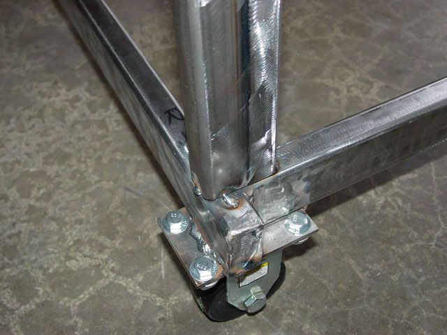
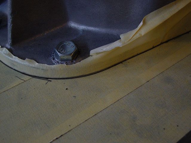
This show the fitment at the bottom of the verticals; I used pieces of flat stock clamped into place as stops to align everything up so that there is no overhang.

Image

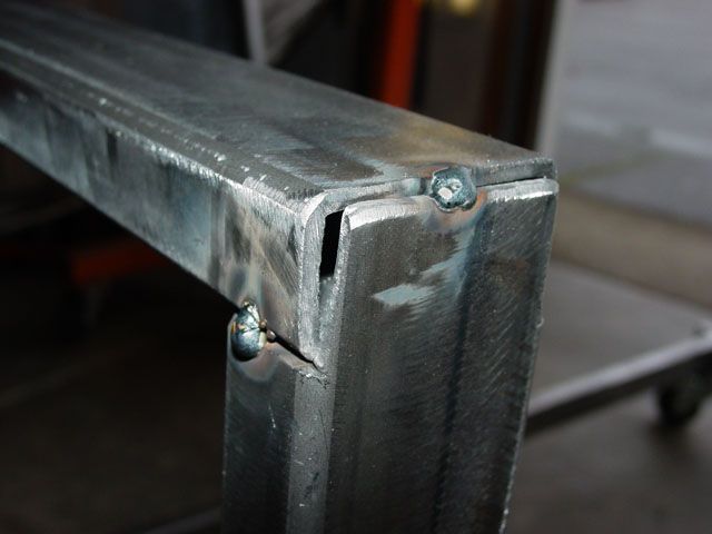
This is how I decided to do the top. As I said, I added 7/8th of an inch extra to act as a stop and a close out. I could have welded the top piece onto the top of the vertical and added a plate at the end but I thought this was a little stronger this way.

One thing I should point out here as it is important. Those of you who ready by body lift on the black buggy remember how much trouble I had welding the kerfs as the seam wanted to shrink in. On the cart portion the seam was on the 1” leg so I put it on the bottom as there is no localized loading to speak of on the bottom. In the 1 X 2’s I got the last time, they had the seams just off center on the 2” leg which is the same as I had the trouble with before; this time, since I am not willing to the loads on the seam side so I intentionally turned the seams to the outside. Any gusseting or bracing will not be loaded or welded on the seam portion of the tube.

The cross tube, which is 22” minus 2 X 1/8th of an inch (tube wall thickness) or 21 ¾ inches long and fits in between the two vertical tubes and sits, as well as the vertical tubes, vertically and horizontally, per a bubble level, where they should be thank you!

Lee

You are close herbie, 35 3/4" so far.
User avatar
fusername
Posts: 6806
Joined: Sun Jan 28, 2007 11:26 am

Re: An engine run cart build

Post by fusername »

I do remember your kerf adventure, gonna steal pelanty of ideas off ur cart design, then disregard them and bolt a bellhousing to the side of a table or something stupid.
give a man a watch and he'll allways know what time it is. give him two and he can never be sure again.

Things are rarely just crazy enough to work, but they're frequently just crazy enough to fail hilariously.
Ol'fogasaurus
Posts: 17881
Joined: Mon Nov 13, 2006 10:17 pm

Re: An engine run cart build

Post by Ol'fogasaurus »

My cart is just my way of attacking this and probably isn't the best way of doing it either. Since my cart/stand is going be a dual purpose engine storage cart and an engine run cart, I am thinking so much of it along those dual purpose lines.

Like other builds I have done, I hope people learn from my mistakes or maybe get some ideas from my way of doing things; hopefully people don't think it is an ego thing... I am too old for that. :lol: A lot of people have helped me now and in the past; I am just passing it on.

On the wall mount: I have seen several of them on different sites and the worst thing I can think of is having an engine nailed to the wall or a post holding up the ceiling and being in the way :wink: . At least this way I can move it around or out of the way when necessary. :roll:

Lee
Ol'fogasaurus
Posts: 17881
Joined: Mon Nov 13, 2006 10:17 pm

Re: An engine run cart build

Post by Ol'fogasaurus »

No actual changes due to a gas water heater located in the garage starting to let go (deformed and starting to weep heavily). The garage floor, while not that flooded (I caught it not too long after it started leaking), is still drying out in the area (and under my work bench cabinets) where I store a lot of stuff. The barber chair, which I have in the garage, became an object of great attention.

I may have a minor change to the design of "crown" part of the stand so I am playing with that. Where the diagonal is shown in the sketch; I could make an "L-shaped" piece doing a cut and notch bend instead of kerfing or heat bending; the bend would have to have a radius of less that 1” to be of any use. The formed piece would give more (area) support to the one bell housing bolt that would have been left unsupported on the 1/4" plate (I am sure it would have been OK w/o the support but the idea of it having no outside support was bothering me (Murphy’s Law: Anything that can go wrong will go wrong and at the most inopportune time”… or something like that).

FWIW:

1. Murphy's Law

If something can go wrong, it will.


2. Murphy's Law

If anything simply cannot go wrong, it will anyway.


3. Murphy's Law

Left to themselves, things tend to go from bad to worse.


4. Murphy's Law

Matter will be damaged in direct proportion to its value.


5. Murphy's Law

The chance of the bread falling with the buttered side down is directly proportional to the cost of the carpet.


6. Murphy's Law

The buddy system is essential to your survival; it gives the enemy somebody else to shoot at.


7. Murphy's Law
Technology is dominated by those who manage what they do not understand.


8. Murphy's Law

The opulence of the front office decor varies inversely with the fundamental solvency of the firm.


9. Murphy's Law

Tell a man there are 300 billion stars in the universe and he'll believe you. Tell him a bench has wet paint on it and he'll have to touch to be sure.

10. Murphy's Law

The first myth of management is that it exists.


The rebuttal to Murphy’s Law is: “Murphy is an optimist”.

“Never attribute to malice what can adequately be explained by stupidity.”

Welding question: I have a 120 volt welder that is supposed to be good for welding around 3/16" thick. I am welding .120 wall rectangular tube and to it I want to add/tack 1/4" plate with about 250#s to 500#s on that (the water pumper engines will have front engine supports so that reduces some of the load on the welds. Should I tack the plate to the stand and have it prof welded or make multiple passes with the 120 welder here.

Lee
Ol'fogasaurus
Posts: 17881
Joined: Mon Nov 13, 2006 10:17 pm

Re: An engine run cart build

Post by Ol'fogasaurus »

Image

Image

I’ve mentioned my “chair” in the garage a couple of times. The area the “chair” normally sits is drying out from the hot water tank taking a dump; so the chair has been move to where I could I take some pictures.

I was talking via. email this am to a guy who I went to high school with; he has a Barber chair also. He also has an old 30 X 30 wooden phone booth in his rec. room along with the barber chair. The fan on the top still works and the old pay phone has been converted so it can be used now days. So cool!

Lee
Steve Arndt
Posts: 7420
Joined: Sat Mar 10, 2001 12:01 am

Re: An engine run cart build

Post by Steve Arndt »

I picture Lee dishing out the old school mafia justice with a rubber hose and that chair.
Ol'fogasaurus
Posts: 17881
Joined: Mon Nov 13, 2006 10:17 pm

Re: An engine run cart build

Post by Ol'fogasaurus »

:lol:
User avatar
fusername
Posts: 6806
Joined: Sun Jan 28, 2007 11:26 am

Re: An engine run cart build

Post by fusername »

My welder is probably slightly smaller than yours, a 100 amp lincoln, I bet urs is a 110 amp. anyways when I am pushing the limit of the machine I use .030 wire isntead of .024 that I use for everytrhing else. I figure the slower melt on the heavy wire helps put a bit more heat into the piece without a huge pile of filler. I also make sure to notch the parts waay hard at the seam, if possible, and fit up w/ a small gap. With 095 tubing I can get a fantastic single pass weld this way, extreemly clean looking and quite strong. If it is a safty part I will make two more passess to be sure, and it still looks good. I sometimes swap out to flux core, which will weld "hottter" at the same settings than gas, and use it for anything over .095. obviously it doesn't look as nice, but its not too bad. When I say I notch heavy, I mean about 60 deg or so, and till the thin side is less than 1/3 thickness or so. My goal is to make all 3 passes, and have pass 2 and 3 actually weld into the base material, root pass, and the other pass, otherwise I am just welding the parent to the old weld, which may or may not have good enough penetration on the thicker part. I also do the last pass on the material I was unable to grind down, so that the surronding material is all as hot as possilbe and hopefully gives me better penetration. My welder says it will do 3/16 in multipass w/ flux core, and 095 should be single pass w/ 025 and a 75/25 mix, but I am calling bulll on that. At least with me behind the controlls. I only used 095 on my cage build due to my lack of confidence on my ability to weld it up. I have made things kind of brittle in hte past pushing the welder, so Istick with what I know I can do.

Take everything I saaid with a salt lick, I am completly self taught based on experience and the internet.
give a man a watch and he'll allways know what time it is. give him two and he can never be sure again.

Things are rarely just crazy enough to work, but they're frequently just crazy enough to fail hilariously.
Ol'fogasaurus
Posts: 17881
Joined: Mon Nov 13, 2006 10:17 pm

Re: An engine run cart build

Post by Ol'fogasaurus »

Thanks fuser, it does make sense. I have .030 tips and, I think, what’s left of a 3# spool of .030 wire laying around but it is years old. I don't know why I hadn't considered going up in wire size or of going with shielded wire. I was going to go up to the welding store in the next couple of days to talk to them about it. Except for the one corner the weld would be an edge weld of the ¼” plate to the .120 tube but tapering the edges might help some I have a welding shop fairly close where the guy does some great work but this was to be a home built job; safety is the watch word here though.

Thanks for taking the time.

Lee
User avatar
fusername
Posts: 6806
Joined: Sun Jan 28, 2007 11:26 am

Re: An engine run cart build

Post by fusername »

The problem with a cold weak weld, is it is very strong. In 5 of 6 possible directions. So a lot of the time a bad weld is still good enough, but it takes only a tiny bit of force in teh wrong direction to take it apart with some wiggling. An engine run car will probably feel those forces due to all the vibration, worst case scenario in my mind. If it is easy enough to take it to a welder, just tack it all together and let him finish, but lean over his shoulder! I'd pay extra to have him let me do that.

I don't know if it is "right" but when I had to weld some very thick steel, a bit over 1/4, to make something tahat didn't need to be super strong last winter, I "preheated" it by putting it over the propane burner of the stove in teh bus while I got prepped, so the ice cold steel wouldn't suck what little heat my mig could make out of the weld area as fast. It was plenty good enough for what I was doing.

I would chamfer the poop out of your 1/4 work piece if possible, and chamfer the 120 as well, buta little less, since the sheer amount of heat you will be putting into it could have you blowing away the 120 on your last pass. Also I would say you have no choice but to use shielded with the size of your machine and the size of the welds in question. I do belive you will need to do a little extra cleanup between passess sice I think the shielded will leave a bit of residue on the bead, but it has been a while since I used my roll of .35 shielded wire, took a while to get the hang of it. You want to weld like a machine w/ it, IE drag in a straight line down the seam, no V wiggle w/ preference towards the heavy sheet like you would w/ solid core. I think you get inclusions from the shielding of the wire when you do that or something. all i know is I kept getting bad welds till I just dragged straight.
also I have heard that using argon mix shielding gass AND flux core wire gives you a bit extra penetration, but i am not sure if that is legit welding technique, or voodoo that makes ya feel better about it.

all said, I would lean towards having a welder finish it for you, 1/4 is alot for a 100 amp machine. If you have anything heavy cantilievered or with a lot of welds in tension, I would err on the side of saftey. If you have a well designed frame that will minimize vibration (I bet you do, knowing you, but I gotta say it) I would weld it, but hammer test a few of your early welds before you get in too deep.

Also the way I cheat when I have issues like this, is redesign a touch so the 120 will have a flange welded to it, which bolts to the 1/4, to overcome my inability to reliably weld something so thick. Of course it could be a bit late in your design process to do that.
give a man a watch and he'll allways know what time it is. give him two and he can never be sure again.

Things are rarely just crazy enough to work, but they're frequently just crazy enough to fail hilariously.
Post Reply