The stress cracking was brought to a head in the late '40s or early '50 when the British Comet had several crashes. They finally found out that the square windows they had were the culprit which caused the stress cracks. There are pix of the stress cracks on line if you look for them. https://www.bing.com/images/search?q=st ... &FORM=IGRE
That was in my time when I was getting interested in airplanes.
Lee
Tucking metal on the edge/Wheel well test piece
-
Ol'fogasaurus
- Posts: 17756
- Joined: Mon Nov 13, 2006 10:17 pm
-
theKbStockpiler

- Posts: 596
- Joined: Sun Jul 15, 2012 10:25 am
Re: Tucking metal on the edge/Wheel well test piece
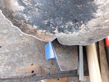
That cut out is for the tank vent and filer hose. Originally it was oval with a sleeve through it. AMC's design was on the cheap but XJ's only weigh 3400 pounds so on a flat surface with no wind it will get about 25mpg highway. The front end of the frame is very thick and wide. It gets lighter and thinner until it reaches the back to the point that there is not much strength at all back where it reaches the bumper. I doubt the last foot is even 18 gauge.  As it was rusted thin but with no holes so I cleaned it up , welded 1/8 inch angle over the top and bottom , made a piece with the cut out with 16 gauge and welded that in between. I went with the smallest hole the hoses would fit through snugly and left it at that. I think the square corner issue is most important if the force is on a angle and splitting the V in the middle.Other wise the force would only be compression on the vertical part of the cut out. In any event It's a lot thicker than what it was originally and hasn't cracked yet. That's actually the second repair I did there in it's history but wanted to get it more solid because of replacing the perch part. So the square cut out has been like that for at least 6 years.
Super beetle with attitude
-
Ol'fogasaurus
- Posts: 17756
- Joined: Mon Nov 13, 2006 10:17 pm
Re: Tucking metal on the edge/Wheel well test piece
"I think the square corner issue is most important if the force is on a angle and splitting the V in the middle.Other wise the force would only be compression on the vertical part of the cut out. In any event It's a lot thicker than what it was originally and hasn't cracked yet. That's actually the second repair I did there in it's history but wanted to get it more solid because of replacing the perch part. So the square cut out has been like that for at least 6 years."
KB, the VW Bug is a unibody car; unibody does not have a separate frame but the whole body, especially the roof and pillars spread/distribute loading around the car. Newer unibody cars spot weld everything together to form a single object which the Bug bolts the pan to the body including a soft rubber gasket between the body and the pan. If you look at what is going on in the muscle car resto field a lot of the unibody cars are now getting frames added rather than tying the front and rear of the car together like I had to do with my V8 Pinto. Even then I tore the seam between the firewall and pan apart from torque.
Like electricity, stress likes to travel down surfaces not through the material itself. It does not like sharp corners or right angle joins very well.
Those of us who run glass buggies are more aware of the loading going on at all times when moving. On my blue buggy, when I built the first of the two body lifts (she second was for my black buggy) when I first climbed inside of the buggy when the body was put back on just the first step over the body and onto the pan, even before sitting down, I could feel the difference. It was that obvious!
As you drive not all the suspension and shocks absorb all the road and other movement; you know, the twisting and flexing that the road delivers. The tunnel is there for a reason besides running tubing through. Glass buggies also have a problem with the tunnel, ahead of the shifter to the Napoleon's hat has a penchant to get a bend because there isn't the rest of the body to absorb a lot of the loading off the front end and inside of the body were you are sitting.
Besides the Comet windows there was the Aloha Airlines 243, 4/28/1988. The airplane thing was caused by the airplane exceeding the number of cycles : e.g., pressurizing and depressurizing of the airplane so stress caught up to it.
https://www.bing.com/search?q=pictures+ ... 3f04516146
A 747 can lengthen close to 2" during the cycle. I got into a design debate on this and it turned out that I was right (the result of a long forgotten discussion I had been involved with).
Scott is very correct on just how important this can be.
Lee
-
theKbStockpiler
- Posts: 596
- Joined: Sun Jul 15, 2012 10:25 am
Re: Tucking metal on the edge/Wheel well test piece
An air planes window is a insignificant amount or area compared to it's entire side. The hole I needed to get the hoses through a 1988 Cherokees frame was a significant amount compared to the depth of the frame.
Super beetle with attitude
-
Ol'fogasaurus
- Posts: 17756
- Joined: Mon Nov 13, 2006 10:17 pm
Re: Tucking metal on the edge/Wheel well test piece
I think you are missing the point.
Even penetrations the size of small bolt holes can fail; I think that was one to the things Scott was trying to make. Even your new fender wells (walls) are going to be spreading loads around. A while back I talked about when you (not your specifically) are bending metal to make joining stiffening flanges from a piece of flat stock the notch needs the relief hole at the "V" end of the notch past the OML of the top of the bend so the material that are being bent don't fight, lift then start a stress riser when the two flanges are welded together.
Deleted as not necessary.
Lee
Last edited by Ol'fogasaurus on Tue Sep 24, 2019 9:13 pm, edited 1 time in total.
-
SCOTTRODS

- Posts: 626
- Joined: Sun Nov 07, 2010 7:15 am
Re: Tucking metal on the edge/Wheel well test piece
Even the smallest panel on ANY commercial airline and likely other airplane, has radiused corners due to the constant and total stresses they endure. If they did not, the corners would definitely stress and crack quickly. While in flight you can watch the wing surfaces "bulge" from growth differences between two adjoining panels. It matters not whether they are the same exact material, as the size of each piece determines the amount of growth within that piece individually as well... comparing the size of a window in a 747, in a ratio, to the side of the plane has little bearing compared to the frame hole in the vehicle. Both are significant in their roles as part of the structure. Won't take long if the hole is not radiuses, to set up stress risers and shortly start the cracking and failures. Drilll stop all abrupt changes in Cross sectional area and at least make it the best it CAN be, or radius all inside corners especially if left as the final edge. Anywhere there is stress, there is potential for failure.
I have found them completely missing more than once. - PILEDRIVER
Some pics of My Powder Coating work
http://s244.photobucket.com/albums/gg6/terrellster/
My Facebook Page for Powder Coating
http://www.facebook.com/profile.php?id=100001788886297
Some pics of My Powder Coating work
http://s244.photobucket.com/albums/gg6/terrellster/
My Facebook Page for Powder Coating
http://www.facebook.com/profile.php?id=100001788886297
-
Ol'fogasaurus
- Posts: 17756
- Joined: Mon Nov 13, 2006 10:17 pm
Re: Tucking metal on the edge/Wheel well test piece
Deleted, A not necessary post.
Lee
Lee
Last edited by Ol'fogasaurus on Tue Sep 24, 2019 9:11 pm, edited 1 time in total.
-
theKbStockpiler
- Posts: 596
- Joined: Sun Jul 15, 2012 10:25 am
Re: Tucking metal on the edge/Wheel well test piece
And now back to our regularly scheduled program. 
If anyone wants to take a big leap forward in their abilities and is up to page 5 in this thread, that is a measure of your self motivation which you will need to be able to make a patch panel. I'm planning on just using this thread for the wheel housing repair to try to keep it from being a saga.
As my last piece was difficult to shrink down the amount needed ,I have considered trying to use different or combined methods to shrink an area.With this piece here , I had to do very little shrinking.
What I did here was I kept the mallet head point just barely in the hammer off dolly range but used a anvil instead of a dolly. On a tight curve this is easy because you can easily get on the side of the center section by working on the sides and or along the curve. The tighter the curve the more shrinking is done. On a straight edge something else has to be done. If the center of a straight edge is rolled up then you can move away from the center, start a curve and it will push the two slightly opposing bends towards each other and cause it to shrink some. The issue here is that the bends don't oppose each other as much as I would prefer. Than you have to do this all the way up to the other edge or as far as is possible. I can't presently see a way to get the bends to oppose each other more if a lot of shrinking is needed. I did do a test on this and abandoned it but I'll try it again on the 3 part of the wheel housing.
If anyone wants to take a big leap forward in their abilities and is up to page 5 in this thread, that is a measure of your self motivation which you will need to be able to make a patch panel.
As my last piece was difficult to shrink down the amount needed ,I have considered trying to use different or combined methods to shrink an area.With this piece here , I had to do very little shrinking.
What I did here was I kept the mallet head point just barely in the hammer off dolly range but used a anvil instead of a dolly. On a tight curve this is easy because you can easily get on the side of the center section by working on the sides and or along the curve. The tighter the curve the more shrinking is done. On a straight edge something else has to be done. If the center of a straight edge is rolled up then you can move away from the center, start a curve and it will push the two slightly opposing bends towards each other and cause it to shrink some. The issue here is that the bends don't oppose each other as much as I would prefer. Than you have to do this all the way up to the other edge or as far as is possible. I can't presently see a way to get the bends to oppose each other more if a lot of shrinking is needed. I did do a test on this and abandoned it but I'll try it again on the 3 part of the wheel housing.
Super beetle with attitude
-
theKbStockpiler
- Posts: 596
- Joined: Sun Jul 15, 2012 10:25 am
Re: Tucking metal on the edge/Wheel well test piece
Before I started this thread ,I did some experimenting on the knowledge that I had at that time. During this thread , my knowledge increased and I had to do the same for this new knowledge. Basically I'm breaking down a whole process into smaller parts to be able to understand it and control it.
Here is my opinion on Locking the Tuck. It's long and may seem over thought out but there comes a time when you have reached the limit of how much a piece of metal can be shrunk and you have more to go so you need to be efficient.
Something I want to address is the process of 'Locking in a tuck'. This is done by hammering down the outside edge of a tuck until it causes a L shape with the top of the tuck. I guess the logic here is that it keeps the top from spreading out to some degree. Instead of the top of the tuck just being a flat shape ;and easy to bend ,hammering the edge/side of it down makes it so if the top shape is changed,the front part has to be buckled or be straightened out. The issue here is that it does not effect the sides of the tuck which absorb a lot of displacement that the tuck creates. With all successful shrinking, metal is stood straight up ; or close to it , and hammered as directly as possible to force it together. A slight bit of releasing is necessary in order to insure that the metal is still 'shrinkable' and not going to fold over on you. Only as much metal should be released that is necessary to ensure this. If this is not done you are at a high risk of bending one side of the tuck over and creating more work for yourself. Releasing by the way is done by not having the side of the tuck stand straight up but by letting it be forced down at a slight angle with the force of the hammer. This makes it so the blow of the hammer both tries to compress the metal but also lets it just change it's angle with the force and not otherwise fold over. There are plenty of videos explaining the 'lock' and the presenter successfully gets the metal to shrink from hammering down the tuck. Most or all of the demonstrations are done with aluminium or metal that highly resembles soft or annealed sheetmetal. The sound seems too soft to me when the hammer hits. So this is leading up to, I don't believe that the 'lock' done as described is doing anything but 'lock' the top of the tuck which is the least amount of displacement in the tuck. If the top was the equal length of the sides it would amount to 1/3 or the entire displacement of the tuck. I discovered early on that most of the procedures and methods of metal working is based on not having more than 2 hands and or special fixtures. To make up for this I would hammer at an angle. I'm not sure this is suggested by anyone else but it worked for me. As I abandoned the lock method because I did not think it was worth the extra working of the metal and hence causing work hardening, I came up with my own method that has decent results.What I do is I make a tuck with a homemade tucking fork ,hammer the outsides in so the sides are closer together but at a slight angle and hammer the one side down with the hammer at a slight angle as well. I either alternate from one side of the tuck to the other or just hammer one side of the tuck down which straightens out the other side without shrinking it. This method may ignore one side of the tuck but hammering the sides really close together before forcing them down does the same thing. I did not want to abandon the lock aspect completely because I knew it had some merit. Prior , I noticed that if you try to lock in a tuck by shrinking the edge completely down and then just try to hammer the rest down with one or two blows is that the edge does not have enough strength and what happens is that it gets stretched back out so there is a lot of working the metal without successful shrinking being done. Just as words change meaning over time I was wondering if maybe the lock method was at one time more involved and too much of the method had been removed for it to work. What I did was ,I made a wide tuck and hammered the outside edge right down. This made two smaller tucks on the corners of the tuck. This seemed to be much more of a lock because it is not just locking in the top part. I worked both of the smaller tucks in ,flattening them and this seemed to be enough to just smack the rest of the inside part of the tuck down.
I would ultimately like to make the two smaller tucks travel up with the shrinking of the tuck but was waiting to receive some better mallets than the HarborFreight ones. The HF ones work but are very light. Some of the mallets I bought were not tough enough.Make sure that you use a nylon mallet to shrink with or the mallet will wear out fast. I'm planning on working on my wheel well project soon in which the contents of this post will be part of.
Super beetle with attitude