Stock 1.8 head flow numbers??
- Piledriver
- Moderator
- Posts: 22520
- Joined: Sat Feb 16, 2002 12:01 am
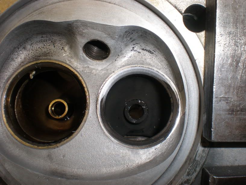
I have mentioned the following musing previously, but this thread is probably as good a place as any to repeat it...HAM Inc wrote: The effectiveness of the ex port is determined by the shape at the bend, not downstream.
...The effectiveness of the ex port is determined by the shape at the bend, not downstream.....................It is a common problem on NA engines with over 11.0:1 compression ratios to push this area of chamber out toward the port. In essence the chamber droops into the port.
One probable aid to the ex. port floor strength issue would be (obviously) more material.
Dangerously following this train of thought strongly indicates a D port.
I have basically an R&D budget of ~zero, but playing with some scrap heads and epoxy stick and my ghetto RIDGID (AKA Shop-Vac) based flowbench, I can get at least the same flow from the otherwise almost stock ex port (guide boss is removed) even when it's filled ~1/3 of the way up with epoxy on the floor, due to being able to actually create a short side radius.
(I'm dying to try it for blowdown with the potato gun setup, but my DAQ card is stuffed)
Semi-on topic:
I bought Pipemax a few weeks ago, hoping to save much manual calculation and maybe for some insight as to intake design (little>no joy there) and it's pretty amusing what ex primary pipe sizes it recommends... Even on large, obscenely high HP engines.
Long story made short, it "says" that a 1.5" OD primary is quite oversize for most of our common appications, and 1.25-1.325" is more like it (under 2.6L/~250 HP--and 1.5-1.625 is about right there)
Also note the port exit should by definition be a little smaller...
It's easy to poo-pooh any "simulator/calculator" program, but Pipemax is sworn by from ~everyone from the guys racing Briggs and Stratton 5HP to the highest levels of engine building. It basically just does the math you would do by hand for you in about 1/10th of a second.
What Pipemax has to "say" (in a roundabout way) about cam duration and timing is interesting as well...
Last edited by Piledriver on Sun Feb 15, 2009 4:20 pm, edited 1 time in total.
Addendum to Newtons first law:
zero vehicles on jackstands, square gets a fresh 090 and 1911, cabby gets a blower.
EZ3.6 Vanagon after that.(mounted, needs everything finished) then Creamsicle.
zero vehicles on jackstands, square gets a fresh 090 and 1911, cabby gets a blower.
EZ3.6 Vanagon after that.(mounted, needs everything finished) then Creamsicle.
- Class 11 streeter
- Posts: 4083
- Joined: Sun Nov 11, 2001 12:01 am
fusername, would you mind plotting Len's last flow figures on your graph for comparisons?
Thanks to everyone for contributing, this is what the type4um is all about..........even the guys wanting part recommendations in the middle of someone else's thread are welcome.......... . Big thanks to warp for getting the ball rolling!!
On another note, everyone please remember as you read this thread, there are no *bad* heads really, but there is a chance at making a *bad* choice of heads for a given engine combination, and most of the time "less is more".
So you think your project is taking forever eh? Well you've got nothing on me.....
- fusername
- Posts: 6806
- Joined: Sun Jan 28, 2007 11:26 am
sure, and are all those figures to be credited to len as well? I like to make sure the og author gets credit for testing and coming up with the numbers.
give a man a watch and he'll allways know what time it is. give him two and he can never be sure again.
Things are rarely just crazy enough to work, but they're frequently just crazy enough to fail hilariously.
- Class 11 streeter
- Posts: 4083
- Joined: Sun Nov 11, 2001 12:01 am
- fusername
- Posts: 6806
- Joined: Sun Jan 28, 2007 11:26 am
Len, do you mind if I distribute those numbers? I would keep the credit to you of course, but if this comes up again elsewhere I would like to be able to share your work to those who are curious.
give a man a watch and he'll allways know what time it is. give him two and he can never be sure again.
Things are rarely just crazy enough to work, but they're frequently just crazy enough to fail hilariously.
- typ4
- Posts: 551
- Joined: Sat Mar 01, 2008 9:46 pm
Len thank you very much for the info, my engine is in a sandrail and the on boost time is pretty short, I have already run into the intake valve control problem with the 48mm valve, 4krpm under boost,10 lbs and it floats like a balloon. Took off the intake tube and it reved nicely till I outflowed my intake. The things you learn by doing..
Again many thanks for the info, I will put it to good use.
2840 type4, turboed and injected with my GM conversion. runs great and still needs fine tuning.
- Type 4 Unleashed
- Moderator
- Posts: 2202
- Joined: Tue Nov 08, 2005 10:43 pm
Hi typ4
You don't have as much of a problem as you think.
Forced Induction doesn't need large ports or valves, and work just as well if you do. Over in Europe, these guys are wild, some are using WEB 277 for turbo cams with Pauter heads.
Even with the valves, your smaller ports will let the Turbo spool faster, and the your springs can't handle a fast spool up either.
What do I think ? Your heads are fine, put some valve springs on, then hold on...
Here's a link to a question I asked about this very thing, I think you will find the info very interesting.
http://www.shoptalkforums.com/viewtopic ... g+pressure
I am getting old, I posted this stuff to your post last year that I just came across, well at least I am consistent on my info...
For me when I do a set of Turbo heads, I will go 46x42, and thanks to Piledriver, I think these springs will be perfect for a Turbo motor, and can stay with stock length valves.
http://psisprings.com/index.php?option= ... view&id=20
You don't have as much of a problem as you think.
Your valve control problem,is because of spring pressure. N/A the springs have to control the weight of the valve, which is over 100g. But with forced induction, the springs have to deal with the turbo pressure trying to push the int valve open, and more so with a larger 48mm valve, and your springs can't handle it.Anyway, I fully agree with the 48mm intake info I built a pair for myself ,they look nice but not welded, and they pretty much suck on my engine.
They work but not efficiently.
This proves my point.Took off the intake tube and it reved nicely till I outflowed my intake. The things you learn by doing..
Forced Induction doesn't need large ports or valves, and work just as well if you do. Over in Europe, these guys are wild, some are using WEB 277 for turbo cams with Pauter heads.
Even with the valves, your smaller ports will let the Turbo spool faster, and the your springs can't handle a fast spool up either.
What do I think ? Your heads are fine, put some valve springs on, then hold on...
Here's a link to a question I asked about this very thing, I think you will find the info very interesting.
http://www.shoptalkforums.com/viewtopic ... g+pressure
I am getting old, I posted this stuff to your post last year that I just came across, well at least I am consistent on my info...
For me when I do a set of Turbo heads, I will go 46x42, and thanks to Piledriver, I think these springs will be perfect for a Turbo motor, and can stay with stock length valves.
http://psisprings.com/index.php?option= ... view&id=20
Richard
EMW
“Have you ever noticed how some people never
have the money to do it right, but can always
find the money to do it twice ?”
EMW
“Have you ever noticed how some people never
have the money to do it right, but can always
find the money to do it twice ?”
-
- Posts: 591
- Joined: Wed Jan 14, 2004 7:33 am
Fusername go right ahead and use my flow data. I get asked for this info all of the time. It is something a lot of folks are curious about.
The photo Dave posted for me is of a valve seat in a turbo head. You can see how the casting drooped and took the seat with it. This is a common problem on most NA T4 heads running 11.0:1 and up, regardless of valve size. It gets worse the larger the valve. I've tried a lot of creative ways to deal with this, but the problem persist. Heat and pressure are a tough combo to beat! Aluminum melts around 1400* and gets pretty damn soft at 1250* which happens to be where NA engines make there peak power. Turbos like even higher EGT's. There just isn't enough material between the chamber and the port. The smaller the ex valve seat, the better!
-
- Posts: 591
- Joined: Wed Jan 14, 2004 7:33 am
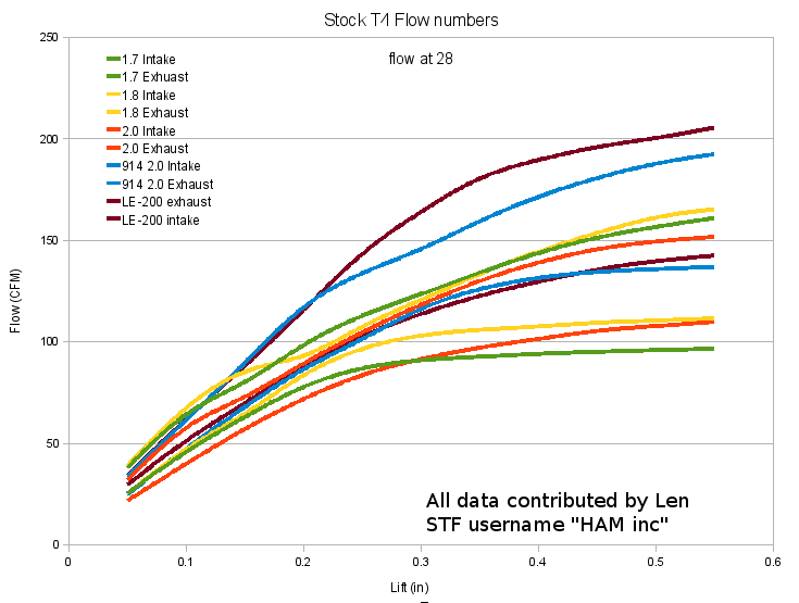
I'm not really sure what Gert hack means by "more area" but here are my observations and what I have found on the flow bench. Up to around .250" valve lift on a 40mm valve the 30* outperformed the 45* slightly. After that the 45* works better and the difference broadens as lift increases.Now that We are at it: How about the 30 degree vs the 45 degree intake seat angle ?
According to the old german tuner, Gert Hack, the 30 degree gives more area -
One thing about 30* compared to 45* is that you have to run a smaller seat ID to achieve the same seat angle width at a given location on the valve face. Meaning if you want a 1.5mm 30* seat width located just inside the valve margin, you will need a slightly smaller seat ID than you would if you were to duplicate those specs on a 45* angle. I know that couple of years ago the NASCAR guys were useing 55* intakes and 50* exhaust. They may still be, I don't know. 30* valve angles are more forgiving to non-concentric seats, tending to wear less in that situation.
BTW there is a great thread going right now on Jakes forum regarding a turbo build. Anyone interested in this subject should register and check it out.
- fusername
- Posts: 6806
- Joined: Sun Jan 28, 2007 11:26 am
I thought I remembered hearing 914 2.0 heads had a 30 angle in them somewhere, am I wrong?
give a man a watch and he'll allways know what time it is. give him two and he can never be sure again.
Things are rarely just crazy enough to work, but they're frequently just crazy enough to fail hilariously.