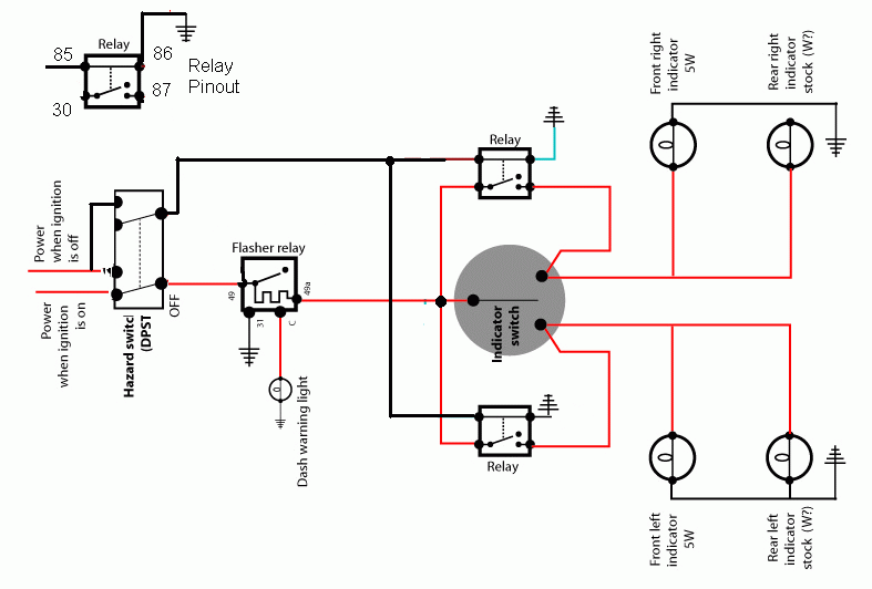
It's meant to operate like this:
When the hazard switch is on, it fires the relays to form a pathway that joins both sides of the car into one circuit to flash all four lights, then when it's turned off, it isolates the left and right sides, so that the turn indicator works (instead of lighting all four lamps off the indicator stalk).
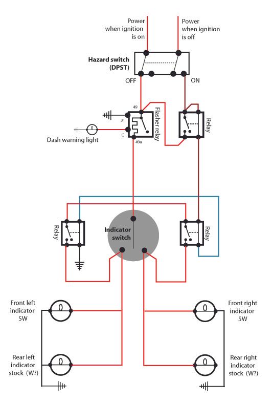
Or here's a link if the image doesn't work: http://i125.photobucket.com/albums/p79/ ... iagram.jpg
(Although it's not shown on the diagram, both power supplies to the switch are fused)
First off, can anyone see if I've made a mistake in my design, or can you see why this wouldn't work? I think I can eliminate one of the relays at the bottom without affecting the outcome of the circuit, but I don't think that would be causing my problem.
I wired it all up today, double checked all the connections were running to the right places and then turned it on. Popped the fuse. Then spent hours popping fuses trying to trouble shoot, but no joy. Occasionally one or the other side of the car would work (fast) but the other side would pop the fuse, as would the hazard switch.
In frustration I put together an electrically identical rig outside the car to check the flasher was working (in case I had a short in the car somewhere). First I rigged it to my two (21W) tail lights and all was good - flashy flashy. Then tied in my two front indicators, one to each tail light, (these are actually side repeaters and only 5w I think). Somehow it fried my flasher relay

This is the electronic flasher relay I'm using (RFL5 part way down the page):
http://www.vehicle-wiring-products.eu/V ... ashers.php
Now I can't think of what to do next? What am I doing wrong?

Any help would be greatly appreciated!
(By the way, I'm in the UK, which has different stop/turn lighting laws to the US. We have separate amber lights at each corner rather than the red stop/turn setup you have on cars in the US)