MegaSquirt-II Success

Fuel Supply & Ignition Systems
Dukster
Posts: 29
Joined: Fri Jun 24, 2005 4:09 pm

MegaSquirt-II Success

Post by Dukster »

:D Having followed some of these posts for 2 years now, and having just completed my MS-II v.3 installation, it is time that I shared my build with the forum. My goals in the build were several:

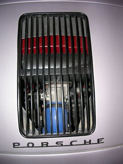
1. Construct an intake system that would fit under the deck lid of my Speedster replica, and that would supply the air volume necessary for a 2180cc developing approximately 150 h.p.
2. Construct the intake system using commonly available materials and easy fabrication skills.
3. Have an engine that would run in a superior fashion to the Weber 44 IDFs that were installed. I was after the drivability of a modern FI engine.

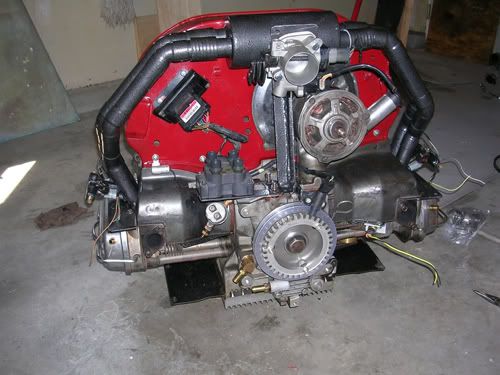
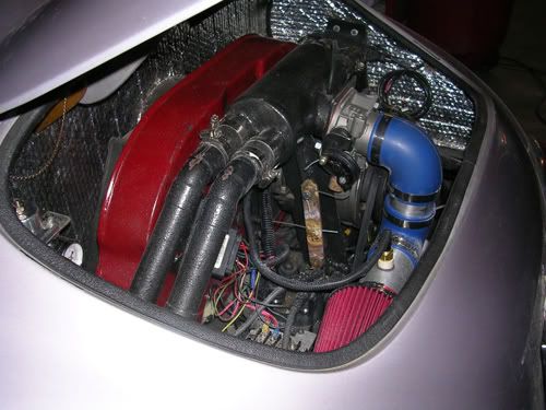
I would post some pics of my engine, but since they have to be posted at some other location on the web first, which they are not, it is more than I want to deal with today. My brain is full!! If you want to see some pics, send me a PM.

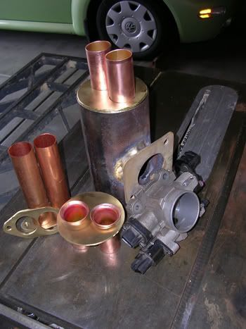
The common problem in converting large ACVW engines over to fuel injection is in obtaining a runner and end casting system that is large enough to handle the air volume needed. The btlmex castings are too small since they were designed for a 1600cc motor. The CB end castings are likewise too small and need some serious modification work to make them flow. My solution was to use 1.25” ID copper water tubing and related fittings. :idea: They are smooth as glass on the inside, and easy to assemble. Each runner has 3-45 degree elbows, in addition to some straight tubing. With the 3 elbows, I could make them snake around the fan housing with no problems.

The shop tools necessary to fabricate this intake system were a 1 h.p. drill press, table saw with a non-ferrous metal cutting blade, oxygen acetylene welding outfit, arc welder, metal cutting composite blade on my circular saw, rotary files, and assorted hand tools.

I rebuilt the motor in the process. Following are the motor specs, with many parts replaced and upgraded:

· New aluminum super block, clearanced for 82mm crank and 92mm pistons. Machine work performed by Rimco.
· Rev-Tru 82mm, forged, fully counter-weighted crankshaft with Chevy journals
· Chevy rods
· Total Seal rings. Cylinder PSI ranges 150-165
· Pistons match weighted to within 1.0 gram of each other
· Full flow oiling system
· 1.5 quart extended sump
· 8.1:1 compression ratio
· Engle V-26 camshaft with new lifters. 297 degrees duration.
· 1.4:1 High Lift ratio rockers
· Hi Torque starter
· Chromoly push rods
· 35.5 x 40 valves
· Silicone bronze valve guides
· Ported and polished, welded-up VW heads, cc’ed to match
· MegaSquirt-II programmable fuel injection
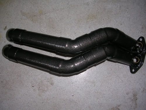
· Large diameter “J” tubes
· 8 Pin flywheel
· Ford EDIS ignition
· 52mm Holley TB
· 20.8 lb/hr. Bosch injectors
· Innovate LC-1 WB O2 sensor


The motor runs cool at a steady 180 degrees, without an after-market oil cooler, while producing an estimated 150 h.p. My goal in building the motor was reliability and cool running, not high horsepower. I am getting to the point that I would rather drive it than work on keeping it together! Also, there are a host of other modifications to my Speedster that are in the planning stage. 8)

Assembling, installing, and tuning a MS-II is not for the faint of heart. :twisted: It is a frustrating experience for those unfamiliar with computers and fuel injection. There is just so much to learn!! What I thought would take 3-4 months has taken 12 months, and I am still in the tuning phase. The work was very part time, with other work and cold winter days taking their toll. The second time around, it would be a whole lot easier. I had no soldering experience with electronics, and still managed to assemble the stimulator, MS, and relay board with no faults. The only fabrication problem I had was in wiring the EDIS unit. A simple lapse of concentration (must be getting old) caused me to ground the SAW wire to the engine through the shielding, resulting in no ignition advance. It took me 6 weeks to figure out the cause.

The most difficult parts for me, since I had little understanding of fuel injection systems and no tuning knowledge, was in attempting to understand the MS manuals in regard to the various assembly options and tuning. There is sooooooooooo muuuuuccchhh to read and then comprehend!! :? Until the flashes of insight start to go off in one’s mind, it is quite impossible to tune one of these systems. Having said that, as with any great endeavor, the feeling of satisfaction that comes with comprehension is wonderful! A positive attitude, reasonable fabrication skills, the patience of Job, helpful squirters, and an understanding wife are all that is necessary. Actually, my wife got a little frustrated because we could not use the car for evening cruises this past summer, and other honey-dos got put on the back burner. Getting an engine successfully MegaSquirted becomes an OBSESSION!

Although I am still tuning the AFR and VE tables, the throttle response is simply unbelievable compared with the Webers. There is no stumble on take-off and drivability is going to be all that I had hoped for. The engine is easy to start in all temperatures and smooth reving. I love the fact that I am no longer spewing clouds of unburnt fuel into my garage when the engine is started from cold. :D

I screwed around with the GM IAC for weeks, until it ceased to function at all. Rather than waste more time and money, I decided to go manual control with the air. :idea: All beetle VWs have heater control levers and cables next to the emergency brake. I mounted a 3/8” ball valve on a bracket where the cable exits its tubing near the clutch. From this valve I ran a length of 5/8” heater hose to a connection I fabricated and that screws down where the IAC valve went. I blocked off the venting passage in the TB where it drew air through the air filter. I also fabricated a small air filter for the intake side of the ball valve. Now, I simply use the cockpit heater lever to control additional air to the TB until the engine heats up. It works great and should never fail!

For you folks who have an interest in my intake manifold dimensions, they are: 1.25” inside diameter runners, 22” long. Plenum inside diameter is 3.8”, with an interior length of 7.65 inches.

I want to thank Bill Steele for his advice and encouragement in this project. He kept telling me that I almost had it completed, no matter how deep I was in frustration at times. Thanks to those truly skilled and knowledgeable individuals on the Fuel Injection forum in Shop Talk Forums, there is a wealth of design and component selection information accessible in search mode. The gurus on the MegaSquirt forum are vital when problems are encountered with that system. Gearheads rule!!

I hope that my success as a newbie encourages others to embark on such a project with their ACVW. These timeless designs will keep getting better as long as there are people willing to adapt the newest technology to them.

Chuck Roach
Wichita, Kansas
[email protected]
User avatar
slowtwitch
Posts: 533
Joined: Mon Nov 08, 2004 9:38 am

Post by slowtwitch »

Sounds like you have a winner. Post some pics when you can :D

pete
User avatar
grelland
Posts: 990
Joined: Fri May 13, 2005 2:47 am

Post by grelland »

Great story, great inspiration, and I would love some pics. If you send it to me I could even post them here for you

[email protected]

roy
User avatar
grelland
Posts: 990
Joined: Fri May 13, 2005 2:47 am

Post by grelland »

Thanks, I received your pics, and here they are:

Image

Image

Image

Image

Image

Image
CLH
Posts: 209
Joined: Sun Jun 22, 2003 6:34 pm

Post by CLH »

very clean install and fab
mschilling
Posts: 1692
Joined: Sat Sep 21, 2002 12:01 am

Post by mschilling »

Whatever happened to Bill Steele? did he finally get his Speedster engine running good?
Steve Arndt
Posts: 7420
Joined: Sat Mar 10, 2001 12:01 am

Post by Steve Arndt »

HotstreetVW told me that he had to quit his project because of a back injury or something along those lines. I hope he is okay.

Very cool manifold!!
Dukster
Posts: 29
Joined: Fri Jun 24, 2005 4:09 pm

Bill Steele

Post by Dukster »

That is right. Bill Steele had an old back injury resurrect itself a few months back, not allowing him to bend over or put an stress on his back. Lately, he advised that he has been on the mend.

Chuck
User avatar
Piledriver
Moderator
Posts: 22776
Joined: Sat Feb 16, 2002 12:01 am

Post by Piledriver »

Slick!
Addendum to Newtons first law:
zero vehicles on jackstands, square gets a fresh 090 and 1911, cabby gets a blower.
EZ3.6 Vanagon after that.(mounted, needs everything finished) then Creamsicle.
Dukster
Posts: 29
Joined: Fri Jun 24, 2005 4:09 pm

Fabrication Details

Post by Dukster »

I have been getting some questions from members who are at least considering building an intake system along the lines of the one shown. Rather than repeat some specifics over and over, here are the ways that I fabbed the intake. Your system and build may be different and there are of course many other ways of building one of these. Use your own judgment on what will work for you.

Brass plate is 3/16” thick. ¼” plate would also work fine
Holes for the 1.25” tubing are cut with a 1 3/8” metal cutting hole saw on a drill
press. You need at least a ¾ h.p. drill press, as smaller ones will stall
Silver solder is used for brass/copper join at head flange
Brazing rod is used for brass/steel joins at plenum
Regular solder is used at copper/copper joins, as it flows into the joins
Plenum is a piece of 4”x8” thin wall muffler pipe
12 45 degree elbows and 8’ of 1.25” copper tubing were used
Rustoleum Hammered Finish paint was used

I used PEX brass connectors for the injector bosses going into the copper tubing. They are silver soldered in place. However, these were difficult to silver solder due to the melting point of the brass. A deft touch is required. Steel bosses would be easier to use since they will take the heat without distortion or melting. If you use the PEX fittings, cut one in half on a 45 degree angle with a hack saw. It makes two bosses. Chamfer the inside edge to ease the entry of the o-ring. It is a good, tight fit. The hole in the copper tubing should be slightly smaller in diameter than the inside of the boss.

The head flanges are easy and fun to make. Take a piece of 2”x3/16” brass about a foot long. I used a gasket as a guide to scribe around onto the brass. Drill all holes in the brass, then cut the parts out on the table saw using a non-ferrous metal cutting blade. Having a long piece of brass makes it easy to hang onto when drilling, and keeps your fingers away from the blade when cutting the parts out. A sabre saw could also be used, but would be slower.

The flared ends for the plenum tubing are likewise easy to make. :D I looked around for a round, steel ball of 1.75-2” diameter. What I found was a cast steel decorative cap that goes onto the top post of a wrought iron fence. A little grinding brought it to enough of a smooth finish to use. With my bench vise fully open, I put the ball on one end of the tubing, a thin brass plate on the opposite end to protect it from scarring, and clamped the whole contraption horizontally in the vise. A little pressure showed the flare starting to form on the end against the ball. To really make it easy and without risking copper splits, I took my torch and heated the flare end to glowing and applied pressure. The end flared right out! Easy to do and great fun!! These were silver soldered into the brass end plates.

The copper tubing is 1 3/8” outside diameter, so will just slip into the holes in the head flanges. Pressed all the way down flush with the bottom side of the flange, I silver soldered these joins. They are immensely strong, and the silver solder has a melting temperature of 1300 degrees F. Regular solder was used for the elbow to tubing joins, which share about a one inch slip join. The solder will flow into the join when sufficiently heated. The melting point of regular solder is 350 degrees F. The intake tubing runs under 100 degrees F, so there is a sufficient margin of safety. The only way that this solder would ever melt is if the engine were to catch on fire, in which event you will not care about the solder. If you have never soldered copper tubing together before, practice on some ½” pieces first. Shine up the copper joins, use flux, and heat the join about an inch back from the edge. Solder flows toward the heat and will be sucked into the join.

You will want to mock up the intake prior to soldering it together. I cut the tubing to length on my table saw. You will have to experiment with short pieced connecting elbow to elbow to get the runners to lay right where you want them and side by side. Prior to mocking up, silver solder the pieces that go into the head flanges and bolt them down to the head. This provides a good, solid base to support your runners for the mock up. When you get it perfect, solder the joins in place. I left about a ½” air gap between the runner tubing and the plenum tubing and joined them with some rubber hose.

Each runner is about 22” long from the valve head to the plenum end plate, and contains about 430cc volume. The plenum has 1,420cc volume, which is about 275% of one of my cylinders. On my 2180cc motor, each cylinder has 545cc.

This was relatively easy and a lot of fun to build. Good luck with your system. If you do build one of these, please post any differences and improvements made.

Chuck
User avatar
raygreenwood
Posts: 11907
Joined: Wed Jan 22, 2003 12:01 am

Post by raygreenwood »

Nice work. One thing that will also help when building a runner set like that....is to make sure that there are no joints or over laps inside of the tube to affect airflow. It should be very smooth. To help that.....buy a flex hone of the proper diameter and add a spring extension rod to it...and hone the insides after assembly with 360 grit or higher to make sure all burrs and joints are smooth. Ray
Dukster
Posts: 29
Joined: Fri Jun 24, 2005 4:09 pm

Thanks for the sizing data

Post by Dukster »

Thank you Ray for the posts on sizing of runners and plenums. We would all be in the dark without your input on sizing. The runners are slightly undersized in volume for my 2180cc, so I increased the plenum size to compensate. At any rate, the air velocity in the runners should be very good. The throttle response is noticeably much faster than with the Webers, and the exhaust is cleaner.

Next time your are in a plumbing department, check the inside of a piece of copper tubing. It really is as smooth as glass.

Chuck
Post Reply