Hope it might help somebody and if you have any questions just let me know and I will try and help you out.
Here is the project of Widening beam with adjusters. Make sure when you do this that you double check everything, remember measure twice and cut once.
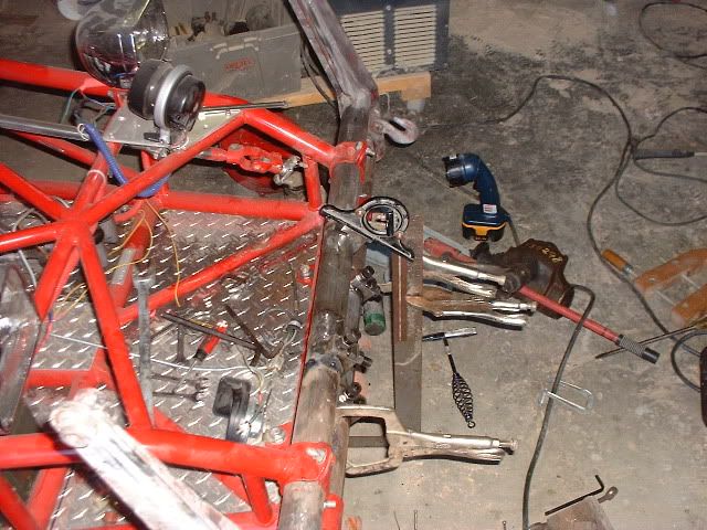
The first is cutting the beam I cut one inch on each side of the middle stock torsion bolt. Before doing this I had measured with arms on at every conceivable location, with and without arms
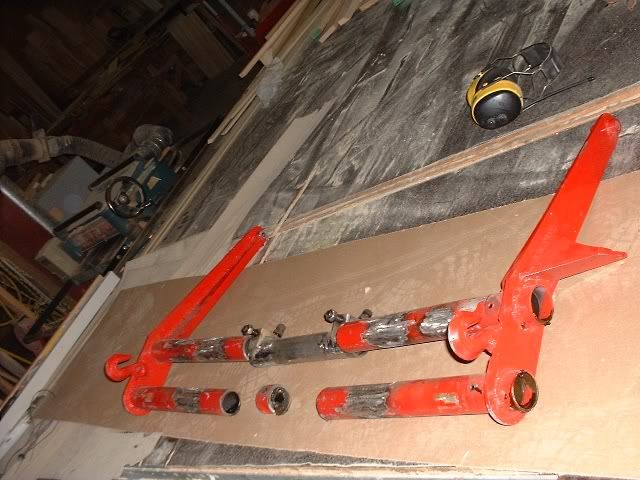
Then I took a 8 inch section of tube from Donor beam but any tube of same diameter and thickness would work. I welded two adjusters to the section of tube and tacked the other two adjusters to the beam. The reason I did this so I would have the width I needed and the ability to get both top and bottom same angle. This was my first time doing this so I went slow and now I know I did steps I could of by passed.
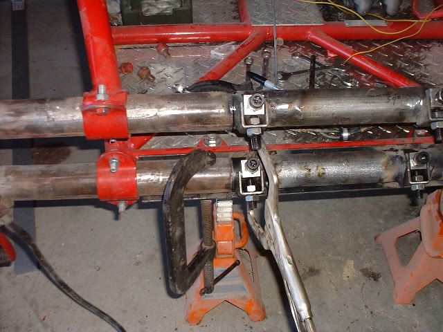
I clamped a section of angle iron behind the beam section to tie in the two ends and make sure the splice went in straight. I used a framing square clamped to an adjustable angle square to make sure my adjusters where set at the same angle. I cut the Torsion plates 3 inches longer then I need and trimmed that down to 1 1/2 once I got the correct distance. That was done by putting arms in with all the adjustment screws taken out so I could mark the location that the indents would be.
I set the adjusters so with the arms, torsion springs and wheels on I could see where the adjusters would be in reference to the height of the beam. I could raise and lower the front of the rail till I got the height that I wanted. What I did was see how high the front end would go till the wheels came off the ground (full extension) which was 17 5/8 so I settled on 16 1/2 with adjusters set in the middle so I could raise or lower the beam. I settled on16 inches of ground clearance, figuring it would settle from 16 1/2 inches.
I clamped the beam in the rail so I would have the correct distance from beam to beam once I had ALL lined up and all adjusters lined up, I tacked all 4 adjusters and two sections of tube to the beam.
Once I got it all tacked GOOD I removed it from the Beam housing and welded up all joints and the grease fittings which I plan on moving to the backside of the beam.
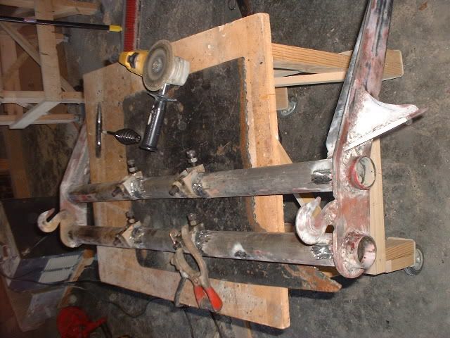
I would weld the seams grind down the tops and weld again. Once I got it all welded I put it back on the rail
Checked everything and took it back off. Like I said I spent alot of time looking and measuring and looking. The wife would come back and I would be standing there arms crossed just looking at it.
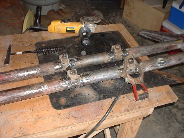
I cut two sections off the donor beam and welded those between the beams for bracing then I took a 1/8 by 1 inch metal strap welded one end to the underside of the bottom beam over the adjuster seam heated the strap up and contoured it to bend over the back of the top beam for both sides. I want to make sure it stays. I took the adjuster bolts out when I slid in the torsion bars so I could make sure that the indents where in the correct location then tightened the bolts to keep torsions in place, then installed the arms, drums and wheels.
I then put the shocks in the lower shock location compressed it 3 inches and marked the location on the shock tower cut the shock bosses out and lowered the tower, notched the brace and welded the shock boss back in. So that way I have shock travel with some to spare. I will also be adding limit straps.
Once I did that I am getting ready to start fabricating the blazer steering box.
This turned out easier then I thought it would and the next should be a breeze. Hope I have helped somebody see it in the process cause I searched alot of places trying to see one from start to finish. I might of made some mistakes if so let me know so that I may correct them now. Again hope this helps!
I took out the floor brace and one other. I plan on adding the floor bracing in. The seat bucket area is moved back 10 inches from where it was at.
I got the Heims in and the Blazer steering box in, tried to get the steering column roughed in but work ($$) got in the way and can't pass that up. Will have more info on it later. Interested in seeing how much bump steer I have now and how much more I can eliminate.
sorry for the blurry pic.
Yea I like seeing everybody @@@@ there head Razz Notice the hi-tech brake line end covers? Have to fab bracing on the back of the box and it should be locked in but won't do that till bump steer is taken care of.
Well after taking the Steering box back out, heims and tie rods different length so had to redo. After relocating several times got bump steer down to a 1/16 of an inch I am happy. Will post pics tomorrow. Alot of welding done.
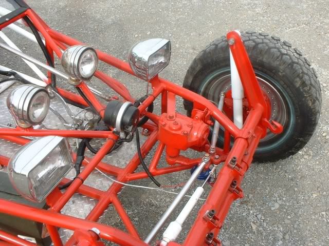
The Blazer steering box is a 1987, when I went to the junk yard and asked them if they had one they said no but looked in the computer, they did have one and it has been sitting on the shelf since 93 had 78k on it got it for $45 with Pittman arm. It was built to be able to handle off road better then the VW steering.
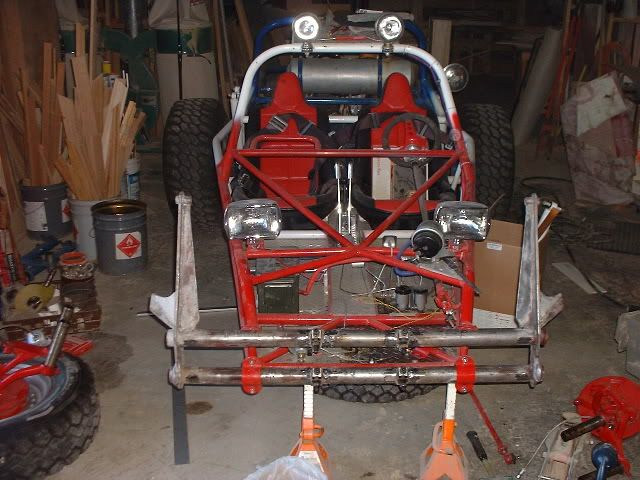
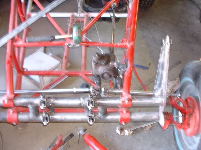
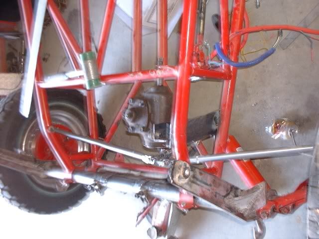
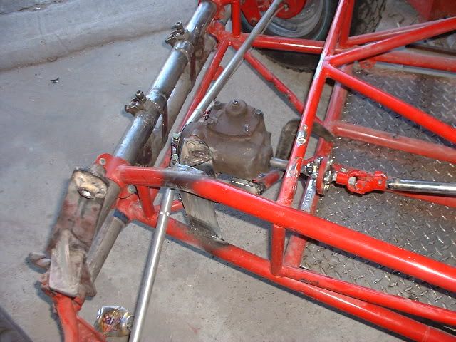
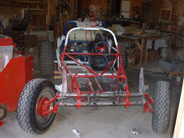
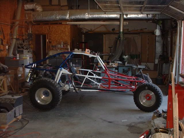
Done with the Front (yeah right) moving on to the floor, steering column,shifter and cutting brakes. The steering with the Blazer steering box is unreal, granted I have not had it on the road but it takes 2 1/2 turns stop to stop and it feels like power steering, no resistance at all, talk about smooth. Still have to move the grease fittings to the back of the beam. Here are some pics in case anybody is interested.
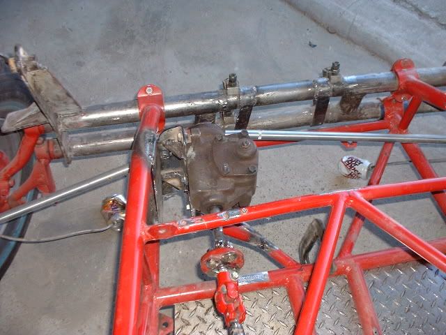
Done with the Front (yeah right) moving on to the floor, steering column,shifter and cutting brakes. The steering with the Blazer steering box is unreal, granted I have not had it on the road but it takes 2 1/2 turns stop to stop and it feels like power steering, no resistance at all, talk about smooth.
Still have to move the grease fittings to the back of the beam. Here are some pics in case anybody is interested.
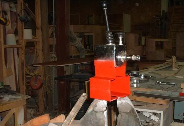
It is welded and braced. Image may have been reduced in size.
Like I said have bump steer down to a 1/16th from full up to full down I can live with that.
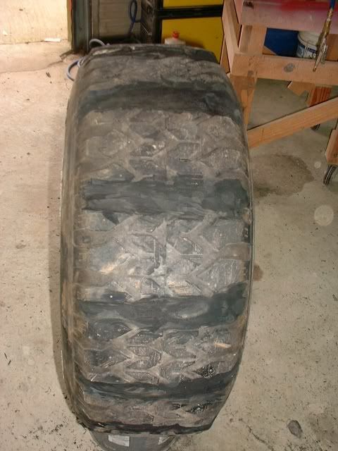
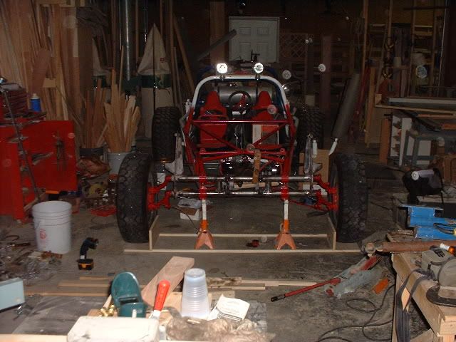
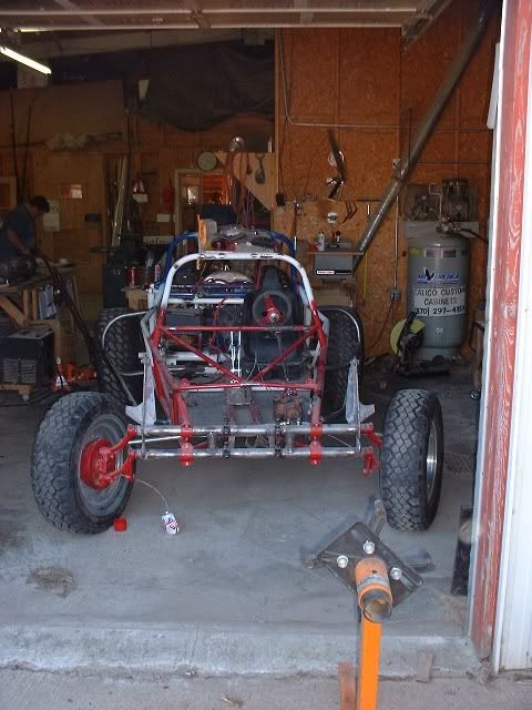
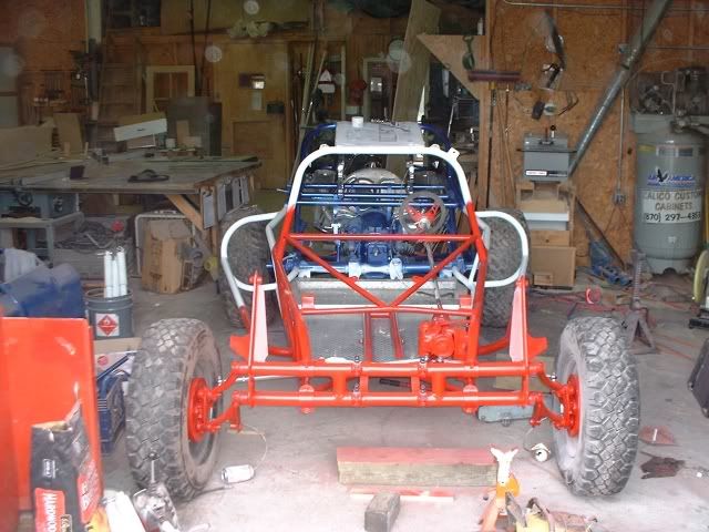
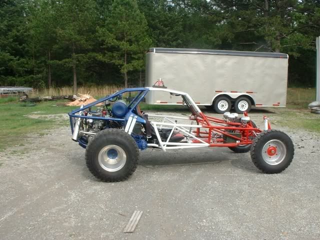
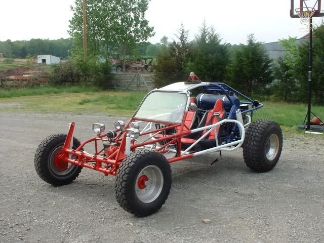
This is a shot from the front I am glad I went with the 10 inch wider front.
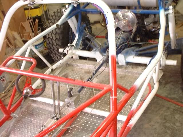
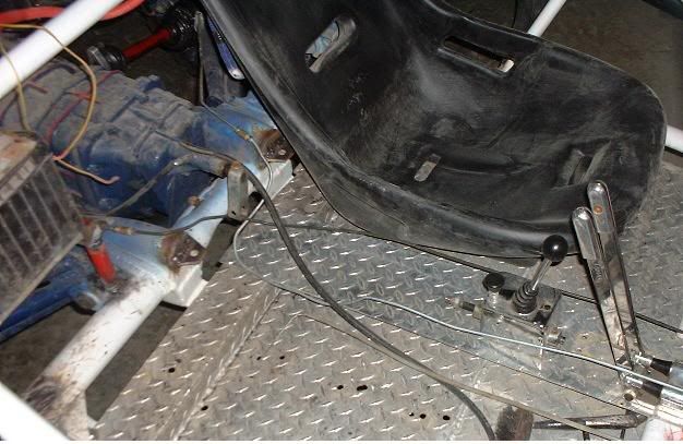
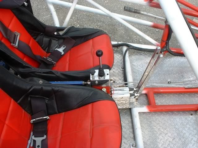
Here is a picture after I moved the seats back, before my knee would get caught between the steering wheel and frame, not now!
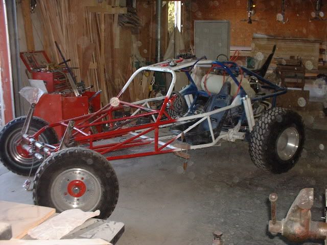
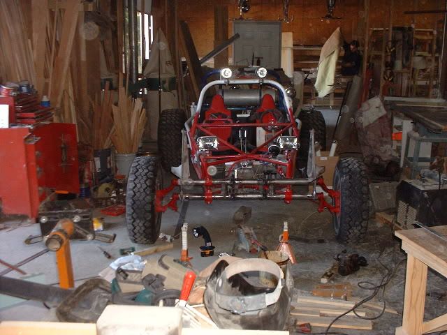
Another pic little dark but I am starting to like how it is coming together.
So far 10 inches wider and adjusters giving almost 17 inches of clearance , the Steering box is big but it was built to handle off road and I think it will handle the ruts and holes alot better then the Stock VW Steering box. Can't wait till I can put some mil-spec paint on it. Now on to the next project.
On the beam I used a donor beam that is also where I got the extra springs for the front. But if you move the adjusters in a little (measure first) in you can get away with using 1 pair of springs vice 2 . I shortened the Shock tower by 2 inches I believe so the shocks would use full movement. I looked all over trying to find somebody who did a ten inch wider beam and adding adjusters and could not so I posted the info I used. After I finished it did not seem as a difficult task as I thought but sure did alot of measuring and looking, alot!
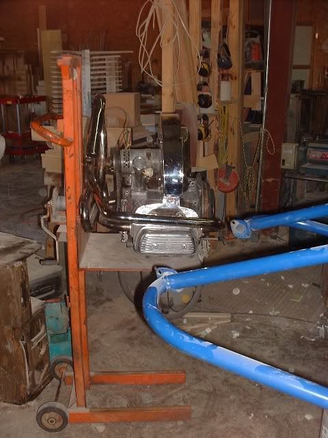
the VW engine, I pulled it out of the rail, I have a dolly ( will post a pic later) that the bed can be raised and lowered so I stuck that under the motor unbolted it, took the slack out and pulled the engine back into the dolly bed moved the dolly back raised it up then pulled it on to a rolling table, cleaned it up set the valves, decreased it including the tin, put new points,rotor,wires,cap on and putting the tin back on. While I am doing that I am taking clear RTV and putting it around the tin where it meets the fan housing trying to seal air leaks. Do not know if it is over kill but figured the more I can keep directed onto the cylinders the better also keeps debris from getting in the fins. Not painting the engine figure no paint is better to help the heat dissipate. Any ideas on that? Well back to play I mean work. Just thought I would write some notes if any interested, if not sorry for wasting your time.
Here is the lift that saved my back just raise it or lower push it up to the tranny and shake like a dog getting out of the water.
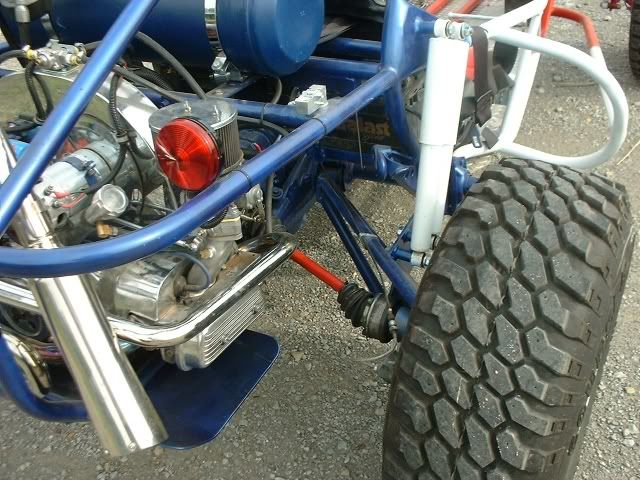
Just some notes put the 27 mm rear torsion bars in 4 times the charm. (yea I am slow) Finally got it dialed in. The springs where set a 21 degree before bolting in, once bolted in and weight was on it sits at 12 degrees with the axles at a 20 degree angle they are 944 CV's so that is as close as I care to get.
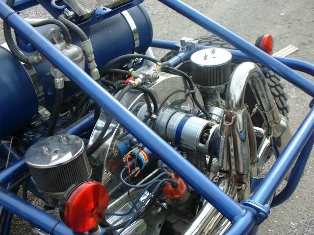
Put the dual Kadrons and linkage on but like everything I'm going to take it back off, weld up the brake light holes that are now behind the air cleaners and relocate them. Trying to figure out if I want to go with stock fuel pump or go with electric fuel pump, either way I need to knock pressure down to 2 psi. so either a regulator or stack gaskets if stock fuel pump is used. Tomorrow clean CV's and reinstall with lock washers this time.
Got the front end on, torsion bars in, tree bars on
Engine back in brackets for lap belts, battery box in,Still have to come up with come up with a couple of tabs for lights. Roughing in cutting brake and shifter. Question, how short is to short for the shift rod? I know it has to rotate, right now mine is going to be (unless won't cycle through gears) 15 3/4 long.
Ok since no one really knows ( or would tell me Shocked )I wanted to get rid of the adapter while having a very short length of shift rod. I did some mods to the shifter to raise it up to the height of the tranny so no adapter is needed. Should work and also be able to mount items to it.
So that is what I started with, where the hockey stick was 6 1/4 higher then the shifter rod.
And this is what I did to reach the height of the tranny hockey stick.
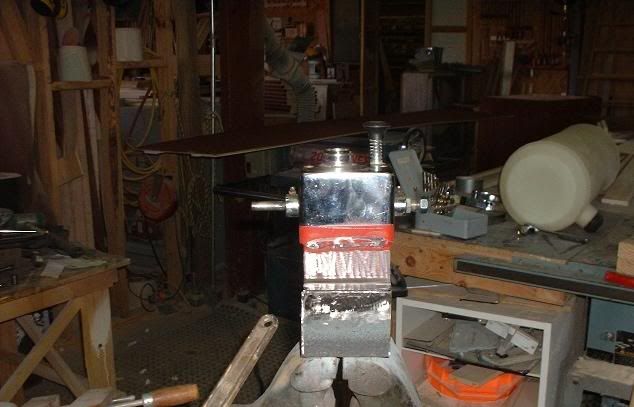
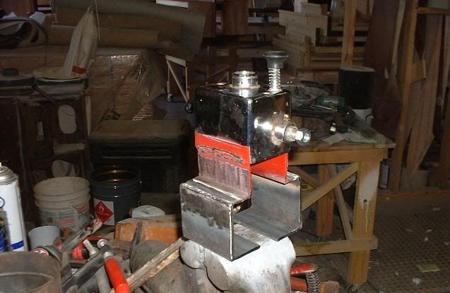
So it will have a straight shot with no adapter. It should work, be glad when all this theory stuff is proven.
Just a heads up, made a template for a windshield for the rail took it to the glass shop, I had a hole in the glass for windshield wiper, not a biggy just more $$ so guy told me 2 weeks again not a big deal. I asked safety glass he said yes I said automobile glass, yes? He said tempered because the hole, so no hole and laminated safety glass 3 days away and $60 bucks. Make sure you specify laminated safety glass.
This is not a good pic but if you look at the aluminum plate you will see the floor has been recessed a 1 1/2 so it drops me down and angles the seat back it has helped out alot, before my noggin would hit the roof.
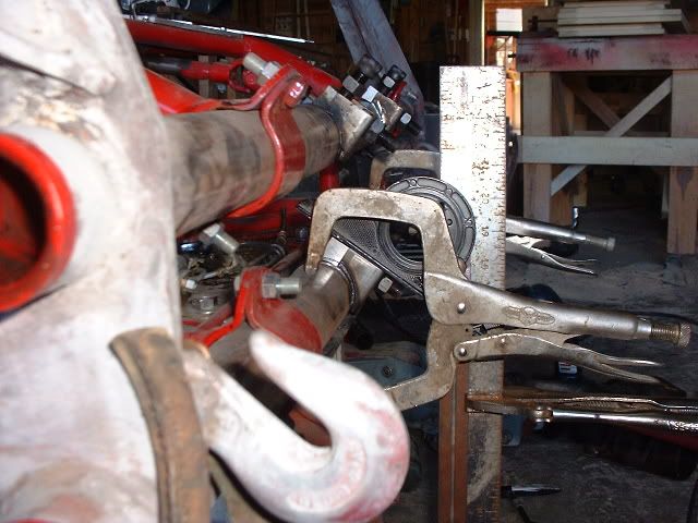
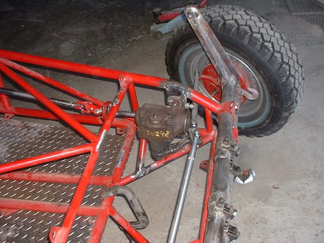
When I did the beam I covered up the holes for the grease fittings so moving them to the back of the beam for better protection. Here is what I found needs to be done to put the new ones in.
I used a 1/4 X 28 tap which calls for a .213 drill bit the closes thing I have is a .218 which equals 7/32 so first I test drill and tap in a 1/8 inch piece because that is also how thick the beam tubing is. Fitting snugs up good but I will add some blue locktite to it for added measure. Next add steering stabilizer and the front beam is ready for paint
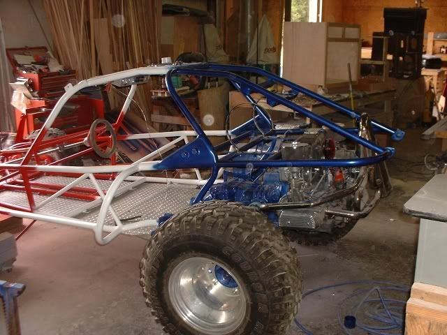
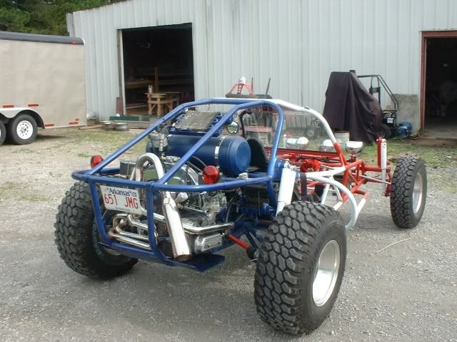
Well I blew the dust off of it and finished the paint, yes same paint scheme, kinda hooked on it. the Blazer steering box, heims and rods rebuilt King and Link pins,
adjusters widen beam.
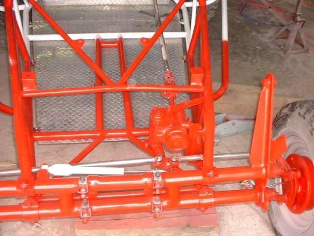
Installed tree bars had a heck of a time finding the right angle pipe fitting Razz Put 27MM torsion bars to replace the stock ones added dual carbs, moved the seats back 10 inches to add some leg room.
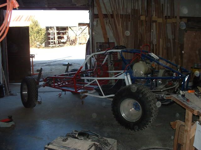
I like the stance of the front end, like the adjustment that I can get should handle alot better being a bit wider, now if those trees will just part like the red sea all will be
alot of hooking up to do including redoing the wiring even though the other was one season old, adding oil buzzer, fused main line and new fuse box. Have to have it done by April 8th. have a ride to go on. So guys what do you think? Paybacks are a bitch huh? Come and get it!!!
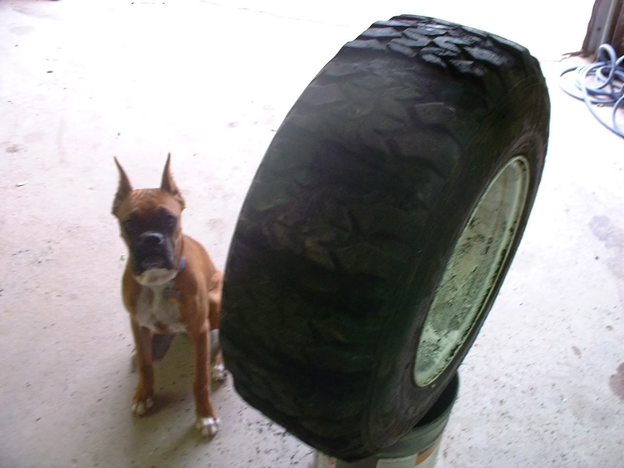
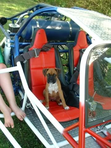
Speaking of bitches here is our new boxer
Ok here are some more shots. Still have some carb work to do and a few other areas but for the most part I am pleased. And for now done!
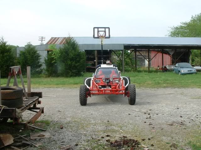
I do like the stance with the front beam 10 inches wider.
Here is one with the blazer steering box, I am glad I did it steering is like having power steering, I don't get the jarring and bumps through the wheel and steering with one hand in corners is not a problem.
Cannot speak for R&P but it beats the stock VW steering by leaps and bounds. Which is also what it handles better.
You can look back at some of the before shots and see a difference in ride height and stance.
Did alot of changes including dual carbs instead of a progressive, electric pump, regulator, spark arrestor/muffler, electronic ignition, getting a SVDA instead of the 009 so that should help also.
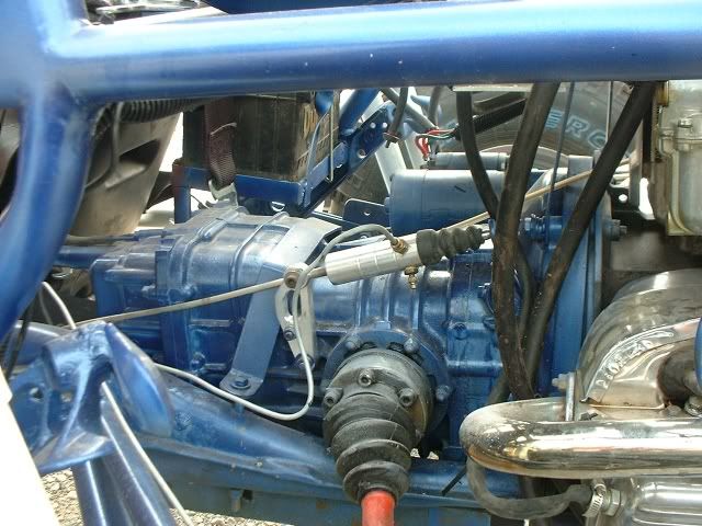
Pic of tranny and Hyd clutch
Seats and shifter, which is now in line with the hockey stick and have alot easier adjustment.
I also put the headlight dimmer switch on the side of the adjuster that way I just hit it and keep going.
Well for now that is it, next big project is the subie engine, HMMM what to put it in?