Ol'fogasaurus black buggy

Offroad VW based vehicles have problems/insights all their own. Not to mention the knowledge gained in VW durability.
Ol'fogasaurus
Posts: 17756
Joined: Mon Nov 13, 2006 10:17 pm

Re: Ol'fogasaurus black buggy

Post by Ol'fogasaurus »

Back working on the buggy somewhat. I am still playing with options on the steering and this time (part of this is a duplicate of the above post) I am back working on moving the steering inboard a bit to get the steering shaft between the pedals not interfering with them.

Image

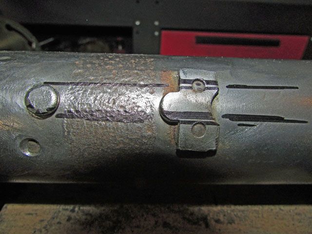
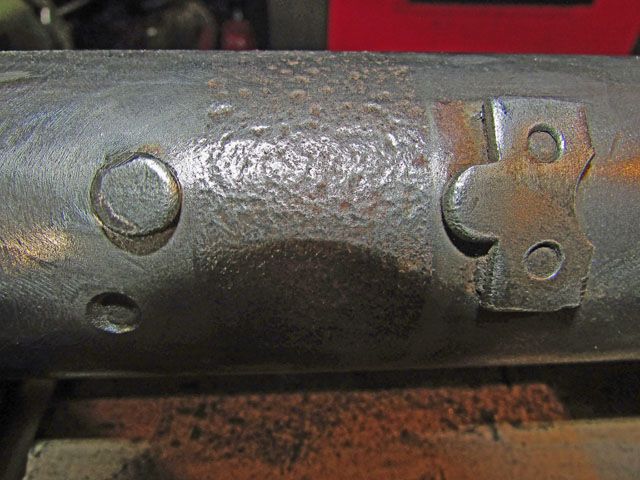
This is the back side of the top torsion tube. These are the two locating stops for the stock steering box. The shock tower is towards the left.

Image

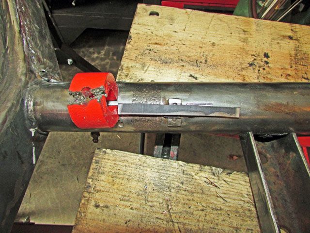
This is what I was proposing in the last post. I would have to trim some of the stops away but...

Image

This shows what I have in mind but in a more optical way. The rod is sitting on top of the button shaped steering box locating piece and on top of the stop on the other side of the steering box. I think I want to narrow down the piece of flat stock, remove the button and the other locating piece and weld in the strip. It may have to be thinned out top and bottom plus height but this would allow me to control the rotation of the steering box but not hold it centered which I am not real concerned about... yet. I have yet to figure out just how far it has to be move but it is somewhere close to a couple of inches. This would/should allow me to keep the same stock steering components and should be cheaper than going full out in some of the ideas I have been playing with.

The tie-rod length change may be something to worry about but I have to find out once the box it located.

As was suggested I may have to relieve the top of the frame head some then reinforce it but I think that is very possible to do.

Opinions?
Lee

My opinion is worth slightly less than what you paid for it.
User avatar
dustymojave
Posts: 2312
Joined: Mon Dec 01, 2008 9:08 pm

Re: Ol'fogasaurus black buggy

Post by dustymojave »

Instead of moving the steering box, how about putting a short section of shaft with a pair of u-joints at the ends to deal with the offset? It would mean putting a support bearing at the bulkhead. Could even mount it to the fiberglass.
Richard
Lake LA, Mojave Desert, SoCal
Speed Kills! but then...So does OLD AGE!!
Tech Inspection: SCCA / SCORE / HDRA / ARVRA / A.R.T.S. OffRoad Race Tech - MDR, MORE, Glen Helen BajaCup
Retired Fabricator
'58 Baja with 955K Miles and counting
Ol'fogasaurus
Posts: 17756
Joined: Mon Nov 13, 2006 10:17 pm

Re: Ol'fogasaurus black buggy

Post by Ol'fogasaurus »

"Instead of moving the steering box, how about putting a short section of shaft with a pair of u-joints at the ends to deal with the offset? It would mean putting a support bearing at the bulkhead. Could even mount it to the fiberglass."

That is where the problem is... room. In the stock location the steering box points to the corer of the body. From the end of the worm gear (with the steering box located in the stock location) there is something like 8" to play with. I haven't marked the body and pan yet to locate the center of the pedals (requires lifting the body up and putting a piece of tape in the center of the pedals spread so I can see just what off-set there really is) as it requires me to lift the body up enough to see what is going on. As I was writing this reply I had an epiphany on how to measure it and went out and tried it... it did work even if there isn't much room. The offset is about 2" and the distance from the end of the worm gear shaft to the firewall/bulkhead is ~ 9' but the fire wall is not straight up and down either and angles forward. With the body lift there the pedals would be somewhat lower than the shaft would be at penetration of the firewall but I haven't measured that yet (I still have to figure out the height the shaft would make at penetration. That should be somewhat easier to do than other things I still have to figure out. I already have a "pillow block" that I could use on the firewall to support the shaft but it is a Napoleon's hat shaped unit designed for mounting on the top of the roll bar's cross-piece; e/g. it has the feet on the bottom (I never paid attention to that until now) has an oil cup and the lid then pointing up. There would not be enough room under the dash (access) for the oil pot and again... the pedals and my #11 "Brogans".

The stock rag joint and brackets take 2" - 3" of room so, for sake of discussion, that shortens the working distance to under 8" between the worm gear shaft and the firewall/bulkhead (I had mentioned a long time ago that the builder did not assemble the three pieces of the body using a jig of some sort so nothing really fit right... but did look good. His making the pieces in the mold wasn't that good either which is why I have had to do so much FG work and still have more to go). I am back to the limited number of options with the sliding of the steering being the cheapest (not the easiest).

One of the reasons I write and ask for help as when writing as I do read them and think hard about them, then when writing replies I do get ideas (this is a common way of doing things [discussions/playing off each other so-to-speak] where I worked and I still miss it. As I write, another potential option might be to replace the rag joint itself with a hard or just bolting the two plates together sans the disc but that too bothers me as there is no strength to the sides just up and down (still dealing with the 48 spline problem) then adapting the universal on the inside of the cabin which is still not a big distance to off-set to closer centering it to the driver's seat (not fully located yet having to do to some ancillary problems not yet solved.

Thanks for the reply Dusty and I am still considering it.
User avatar
Leatherneck
Moderator
Posts: 17104
Joined: Sat Jul 01, 2006 6:47 pm

Re: Ol'fogasaurus black buggy

Post by Leatherneck »

As far as Tie Rod length, Speedway and others have them in many sizes and materials. Not a worth worrying about.
Ol'fogasaurus
Posts: 17756
Joined: Mon Nov 13, 2006 10:17 pm

Re: Ol'fogasaurus black buggy

Post by Ol'fogasaurus »

Thanks Leather, never thought about them for VW stuff. It's been a long time since I either had a catalog of theirs or visited their web site.

Lee

I just checked and the only Speedway catalogue I have left is #206 which is a 2002 edition. :roll: :lol:
Ol'fogasaurus
Posts: 17756
Joined: Mon Nov 13, 2006 10:17 pm

Re: Ol'fogasaurus black buggy

Post by Ol'fogasaurus »

Question:

is the worm gear shaft on the stock VW steering box 3/4" dia. X 48 spline?

Is the steering shaft have an internal diameter of 3/4" X 48 spline?
Ol'fogasaurus
Posts: 17756
Joined: Mon Nov 13, 2006 10:17 pm

Re: Ol'fogasaurus black buggy

Post by Ol'fogasaurus »

Got some garage time today so I dug into the steering box to firewall relationship and the steering shaft gong through it problem.

I took the steering box off and put a 2' long combination square on the beam using the center of the steering box locating pieces on the beam as my starting point (if you notice the locking devices are located pretty much straight under the worm gear shaft). With the car up on jack stands with the stands on the dollies it sits up height enough that with the driver's side wheel off (I am using home made "hubs" for transport because on the dunes I will be changing over to spindle mounts) so I can sit on a lowered stool and am able to see some of what is going on (it is still awkward to see much but it keeps me from laying on the floor which is just as awkward when looking over the beam. By-the-way, smacking your head on the edge of the FG fenders/wings is no fun and you can get cuts that way).

Using a flashlight is awkward but does help some in locating things. You can put a piece of tape with a hole in it over the opening for the light to come out and get a locating spot. Using two pieces of tape with the center open you can get a light stripe; both can be used for centering where the steering box would sit in relation to the fire wall but is doesn't give me the piercing angle. I just had an epiphany : the 48 spline diameter of the steering shaft/worm gear shaft is just under 5/8ths of an inch so, making a tight slide-in adapter to temporarily mount one of those small 3 led flashlights to the worm gear shaft might give me the piercing angle/height off the floor that I am looking for. Hmmm!

It turns out that the steering shaft pierce through the firewall relationship is pretty close to the outer bend (for the rise) in the Napoléon's hat which is about where the pedal split on my hydraulic conversion is so I should be OK there. With the 3" body lift the pedals sit down low enough that were the pierce is could be OK. I need to find that out as a check then locate the steering wheel in relationship to the driver's seat. I think it is close to where it will be but I had to get my short leg model over to check where I am on the seat to tunnel location is. I'll have to check my notes but I think the steering wheel C/L (centerline) is something like 22" off the floor at the dash board.
Lee

My opinion is worth slightly less than what you paid for it.
Ol'fogasaurus
Posts: 17756
Joined: Mon Nov 13, 2006 10:17 pm

Re: Ol'fogasaurus black buggy

Post by Ol'fogasaurus »

Now that the new tool box is done I am back on the black buggy. I have a pair of Race Trim seat mounts, I think the 4" high units. The seats I have are some older (but new/unused) wide seats. I originally centered them in the seat mounts with the seat mount being off-set towards the tunnel about as far as I could get them but still allowing hydraulic lines to pass by them.

After slotting my home made adapter mount (a piece of plate) some I am still not far enough over to allow the seats to go full forwards (~6" of travel) due to the taper in the body and pan. I just did some measuring and putting the turning brake assy over the e-brake hole in the tunnel and back a bit to miss the bus shifter I have about a max of an inch of additional movement before interfering with the turning brake handles. I don't plan on using the hole in, maybe a half an inch at the most (will see after some more slotting).

With the seats moved max (as I want them) over towards the center a lot of the potential weight will be on the one inboard leg, maybe up to 250#s plus bouncing around weight changes which is where I am kind of stopped right now: e/g/, I can't seem to find any specs on the loading figures on the Race Trim seat mounts. Does anyone know facts or where I can find them?

Thanks Lee
Ol'fogasaurus
Posts: 17756
Joined: Mon Nov 13, 2006 10:17 pm

Re: Ol'fogasaurus black buggy

Post by Ol'fogasaurus »

Getting back to the rear suspension and brakes I am going to have to make a change to the trailing arms by adding a new brake line connection tab on the inside of the trailing arms rather than the stock location on the outside of the trailing arm.

http://www.mooreparts.com/mounting-tab- ... s-slotted/

An example of one of the mounting tab kits available.

Image

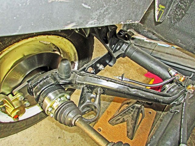
This is the driver’s side trailing arm and disc brakes I have.

Image

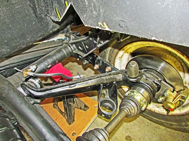
This is the passenger side.

Notice that the disc brake’s connection of the hard line to the caliper is down low compared to being on the upper part of the backing plate like a drum/can brake would have.

The soft brake line connection is on the top of the torsion tube close to the pivot point.

The mounting tab for the soft line on the trailing arm is fairly close to the pivot with to the stock drum brake connection tab making it so the hard line runs down the trailing arm to the outside of the arm. This works well for a top connection needed with drum brakes but for disc brakes the join but is awkward for the lower connection with the disc brake caliper.

I will have to put a mounting tab to the inside of the trailing arm close to the pivot and maybe towards the top of the trailing arm to make the connection to the disc brake easy. I think there is going to be enough room going over the trailing arms seam so that the lines will not have a high spot for air to collect. I will have to do some experimenting to make sure of this.

In the photos the trailing arms are on the stops for full hang.

Lee
User avatar
Piledriver
Moderator
Posts: 22520
Joined: Sat Feb 16, 2002 12:01 am

Re: Ol'fogasaurus black buggy

Post by Piledriver »

Leave it be and run it over the top.
Far less likely to get caught on stuff if its not exposed.

It can make bleeding the brakes a little harder, but a power bleeder takes 5 minutes and about $15 to make...
(You may have the required junk lying around, making it "free")
Note quart size brake fluid container caps fit VW brake fluid reservoirs well enough to seal (may need a rubber gasket).

Speed bleeders also work well if bleeding solo, although the thread sealant on them isn't usually brake fluid proof, which is idiocy... I think they try to make them single use doing that.
Clean the original goo off, put them in with a drop of blue locktite, break them loose 1/4 turn before it sets.
Snug down when done bleeding and stick a cap on it. The threads will be sealed well enough for a few cycles/years.
Addendum to Newtons first law:
zero vehicles on jackstands, square gets a fresh 090 and 1911, cabby gets a blower.
EZ3.6 Vanagon after that.(mounted, needs everything finished) then Creamsicle.
Ol'fogasaurus
Posts: 17756
Joined: Mon Nov 13, 2006 10:17 pm

Re: Ol'fogasaurus black buggy

Post by Ol'fogasaurus »

Piledriver wrote: Sun Jun 25, 2017 11:45 pm Leave it be and run it over the top.
Far less likely to get caught on stuff if its not exposed.

It can make bleeding the brakes a little harder, but a power bleeder takes 5 minutes and about $15 to make...
(You may have the required junk lying around, making it "free")
Note quart size brake fluid container caps fit VW brake fluid reservoirs well enough to seal (may need a rubber gasket).

Speed bleeders also work well if bleeding solo, although the thread sealant on them isn't usually brake fluid proof, which is idiocy... I think they try to make them single use doing that.
Clean the original goo off, put them in with a drop of blue locktite, break them loose 1/4 turn before it sets.
Snug down when done bleeding and stick a cap on it. The threads will be sealed well enough for a few cycles/years.
Thanks for the "put" Pile, I will give what you have said a lot of thought. Right now, without an engine in place, it is hard to see interference by moving them. Going to be down at the dunes at the end of the week so I will look at my other buggy and see if there is anything to worry about.

Since I use headers that go over the top and to the side of the engine (heat rises hence getting the heat loss from the exhaust away from the engine) and there is no bottom shroud (sand likes to collect there and block heat dispersion) some of the potential problems may not be there. Remember I am running on the sand and only have rear brakes so there are only the occasional wrecked quads pieces to run over. I do stop for damaged riders though :wink: .

Since I am going to have to bend new lines anyway moving them to the inside does make it easier, or at least it looks that way but I will double check before I do anything. Thanks again for that advice as I probably would not have even considered it.

I don't think I am going to have room for a power bleeding. I'm pretty sure I'll have to remove the driver's side spindle mount just to get to both of the reservoirs (remember I rebuilt that whole area to put a rail type of hydraulic pedals assembly in). The steering shaft is also going to go in the same area and will split the pedal assy but a bit higher so there will be some access. Add to that it is a tight fit under there and the "wing" style fenders tease you into thinking there is more room than there is. Hopefully bleeding brakes in a glass buggy is a once every few years trial of patience and friendship.

On the seat mounts: since I haven't been able to find any information on the seat mount structure/loading I am currently thinking I will put an intercostal between the inside legs and the upper part of the tube since a lot of the passenger in the seat loading will be more to the inside than spread evenly over the seat mount.

I bought a bead roller late last year, just before we headed south for the winter, and this will give me a reason to build a mount for it and strengthen it up (per videos on the web) any maybe power it too. I might need to add an intercostal between the rear legs also. Not sure but I will have to look into it more but after I get the seat mount in place. I may need to use it for the upper mounting point for the intercostal.

I don't think I have ever heard of "speed bleeders" or have forgotten about them.

Thanks again as it got me remembering then looking at things a bit differently.

Lee
User avatar
Piledriver
Moderator
Posts: 22520
Joined: Sat Feb 16, 2002 12:01 am

Re: Ol'fogasaurus black buggy

Post by Piledriver »

Speed bleeders simply have check valves in them, make life easy bleeding solo, its just that the thread sealant they come with is ~useless, sold at any parts store in just about any size. Just put a cap on them to prevent rust.
Addendum to Newtons first law:
zero vehicles on jackstands, square gets a fresh 090 and 1911, cabby gets a blower.
EZ3.6 Vanagon after that.(mounted, needs everything finished) then Creamsicle.
Ol'fogasaurus
Posts: 17756
Joined: Mon Nov 13, 2006 10:17 pm

Re: Ol'fogasaurus black buggy

Post by Ol'fogasaurus »

Ahhhh! Thanks.

Lee
Ol'fogasaurus
Posts: 17756
Joined: Mon Nov 13, 2006 10:17 pm

Re: Ol'fogasaurus black buggy

Post by Ol'fogasaurus »

I had an interesting experience yesterday when I went up to buy some fasteners for the blue buggy so I could install my truss bar. The bots for the shocks are 12mm and have a 1.50 thread count. The "grip" I am dealing with is 4 1/2" (SAE) on the inside of the shock tower and between 1.8th and 1/4th inch for holding the engine case adapter in place before the nut goes on.

Where I went to was a "fastener" store but they do sell things allied to fasteners, in general. also. The "grip" is the stackup of things I am trying to clamp together including the Kaffer bar ends, the Bilstein shock and their adapters/spacers, and the shock casting of the torsion bar. I wanted to get a shank as close to that as I could w/o putting the threads in "shear". This fastener store is close to where I used to work in aircraft but I have since found out that they only stock "standards" of the "mockup" quality, not flight quality. SAE fasteners usually are designed to be available in 1/8th inch lengths or some in 1/32nds inch lengths. The "box" stores usually stock in !/4th inch variations as it is more economical for them to do so and most people are not quite as finicky as engineering would be. Mockup quality is quite a bit less than flight quality and I wasn't looking for that anyway.

Having been retired for a long time now I haven't worked in metric (at that time the request for us to go metric was inconceviebly expensive as it would have required redesign of almost the whole airplane plus require new designs for repair pieces for the new designed airplanes. The airlines would have to double up on spares and know where each airplane was so that their spares would be able to follow them as they moved from long flights to short flights... confusing isn't it) that much so I was totally surprised in what I got. I ended up getting 2 M12-1.75 X 130MM (length) and 2 M12-1.75 X140MM (length) fasteners. The shank (measured under head to the start of the threads) on the shorter one was 3 1/2" ad the longer one was ~4" which means that some of the load could be on the threads. Since I am not sure just how long of fasterners I needed I got the two closest lengths that were available.

I should know by Friday or Saturday which one, if either will be the fasteners I will use. I also have another problem as there is some electrical doodies that are going to be in the way of adjusting the gension on the Truss/Kaffer bar so they will have to come loose then moved out of the way a bit.

Anyway, for what it is worth.

Lee

I forgot to mention that I also had to go to a courser thread and the bolts are grade 8.8.
Ol'fogasaurus
Posts: 17756
Joined: Mon Nov 13, 2006 10:17 pm

Re: Ol'fogasaurus black buggy

Post by Ol'fogasaurus »

I got one of the longer 12mm bolts allowing me to put the Truss bar in my blue buggy; it looks like everything will be OK assuming I can get some of the electronics loosened up to allow me to wind the Truss bar up tight. I'll try to post a picture of the problem (see below) if I can.

(I tried to post a picture here of what they are posting on this site to me instead of posting any of my photos)

I'm not sure if this is going to show you what I am getting right now but it looks like Photobucket is going to charge me to continue to use their service because I am using it for 3rd party usage. This and the email I got today (a duplicate with them wanting my log-in and charge card) just might be the last straw. Add to that some PMs I have had over the years and other comments over the years I might drop out as it just isn't worth it anymore; I need to cool off first. If you are wanting to get any of my pictures then do it now as it looks like they might be gone before long... if not already.

My files have been tightly secured but lately I have been getting challenged, by Photobucket, as to how I am using their service and wanting to charge me to not get ads. This last bit came with the reasoning they don't like me using their site to do 3rd party posting and not avail myself of using their money making features like the printing of pictures. I have also had my pictures removed and have seen them or copies posted sometimes with other people's name tied to them.

While I know there are other options I just am not sure if I want to futz with it. Also, it seems that some of my posts here are being blocked also.

Lee
Post Reply