Deserter GS to Suby EJ20 Turbo

Are you one of those confused people who can't make up their mind?
User avatar
GS guy
Posts: 909
Joined: Wed Nov 06, 2002 12:01 am

Deserter GS to Suby EJ20 Turbo

Post by GS guy »

I think it's about time I started my own thread about my conversion perversion.
This has been a looooong term project and has gone through a couple of "game changing" ideas before ever hitting the street.

So the story begins about 7 years ago I wanted to build a fiberglass body buggy. Always liked them as a youngster and 70's teenager, and in searching for an easy to build car project - what could be easier? :D :?

During my searching for a suitable candidate for restoration, and having been out of VW's for about a decade or so and catching up there too, I came across a Deserter GS for sale. This was a ready to drive car and big bucks. To me the "ultimate" street bugy - light weight, mid-engine, Big motor - the exotic of buggies! I'd read and oogled over these as a kid, but figured by now they were pretty much "unobtanium".
Well, this sale didn't work out but in the process I was able to pick up a lot of knowlege about the cars and now nothing else would do! I lucked into another GS I'd come across during my searches - but a basket case and needing 100% going through. I'd been hoping to start with a little less of a "project" and more of a driver, but for these cars - if you can even find one that's going to be your one chance! With some minor negotiations it was my new dream machine.

Original plan was a straightforward going-through, freshening up what needed it and mostly a "stock" build. After all, though it literally came in baskets and cans of parts - it was more or less 100% there. Upon closer inspection though, I could see most of the hardware, gauges, engine, trans, pretty much everything was way worn beyond a light freshening-up state.

Back to the conversion - the supplied Corvair 140 engine it seemed like a good starting point for a flat 6 hot-rod project. Lots of research ensued, hanging out on Fastvairs and similar 'Vair boards, picking up everything I could on the potential of the old engine. Though available and relatively plentiful, performance Corvair parts do command a premium. This led to a long thought battle - keep the 'Vair or swap something in more modern? I was wanting into the 200hp club and while the "Vair would do it, it also got pretty high strun in the process. I researched, measured, and diagramed in about a dozen different engines - from the Vair & VW, to Porsche flat 6, V6's, even the BOP/Rover aluminum V8 and in the end the Subaru just made the most sense. It easily supported the HP goals (in stock form too!), low CG, and seemed to fit the chassis as a close to direct bolt-in (however, this was later proven to be not quite the case).

So now the goal was to procure and install a JDM Suby EJ with as few mods to the chassis as possible. Still staying with the "just freshening it up" idea, but now with a modern powerplant. That rose colored vision didn't last too long...... :roll:

More research into transaxles now, as I was questioning the ability of the swingaxle handling the Suby hammer. Especially if I decided to later crank it up a little since HP up into the 300 zone seemed easily doable with the solid Subaru foundation. The conclusion of this research resulted in obtaining a Porsche 914 transaxle and having it gone through. This was about 5 years ago - well before I became aware a Subaru 5-speed could be easily converted to mid-engine use. By that time (a couple years ago) I was too far into the build to start swapping transaxles. While the 914/901 box isn't ideal with the fragile 1st, 2-4th are much stronger and guys have been running them with Chevy small block torque for decades with acceptable reliabality (if not abused that is!). It also fairly closely matched the VW swingaxle in overall dimensions making fitting it to the chassis relatively straightforward - which the Suby trans OTOH would not be.

But wait - the 914 uses CV jointed axles, not swingaxles. Enter full rear suspension re-design to 5-link. Enter major rear chassis re-design to support the suspension (and later realized conflicting points between EJ and original chassis). Enter, "well now that old trailing arm VW front suspension won't do either" and front suspension re-design. The years dragged on with studying suspension design, researching suitable parts, and purchasing the tools to pull it all together. So much for an "easy" project! :lol: :lol: :lol:

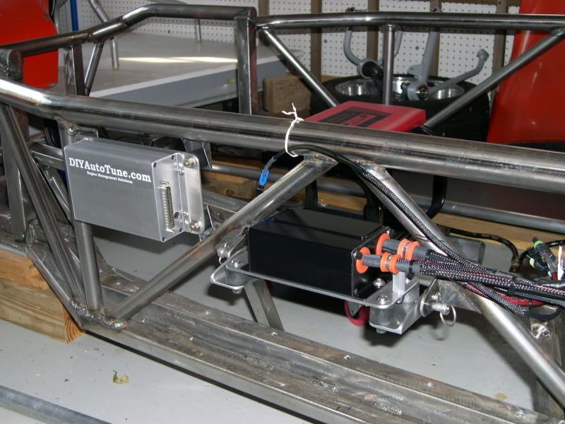
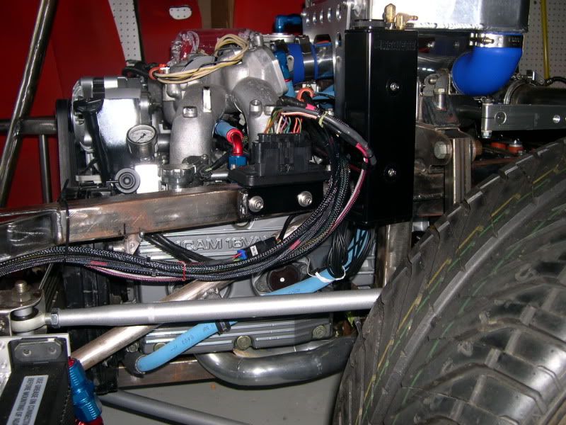
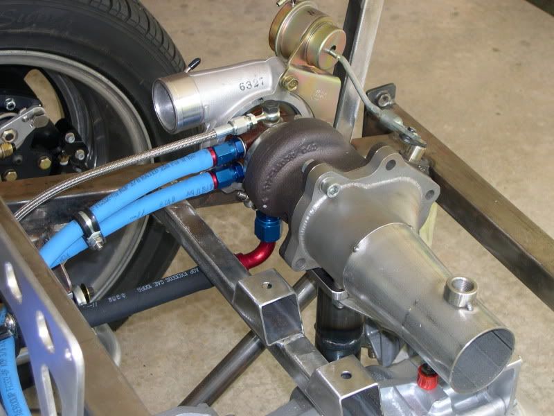
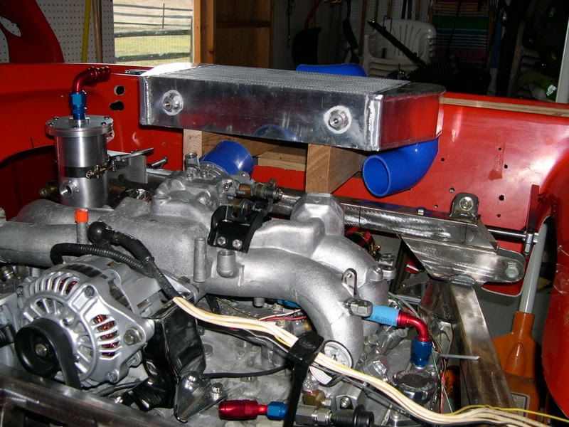
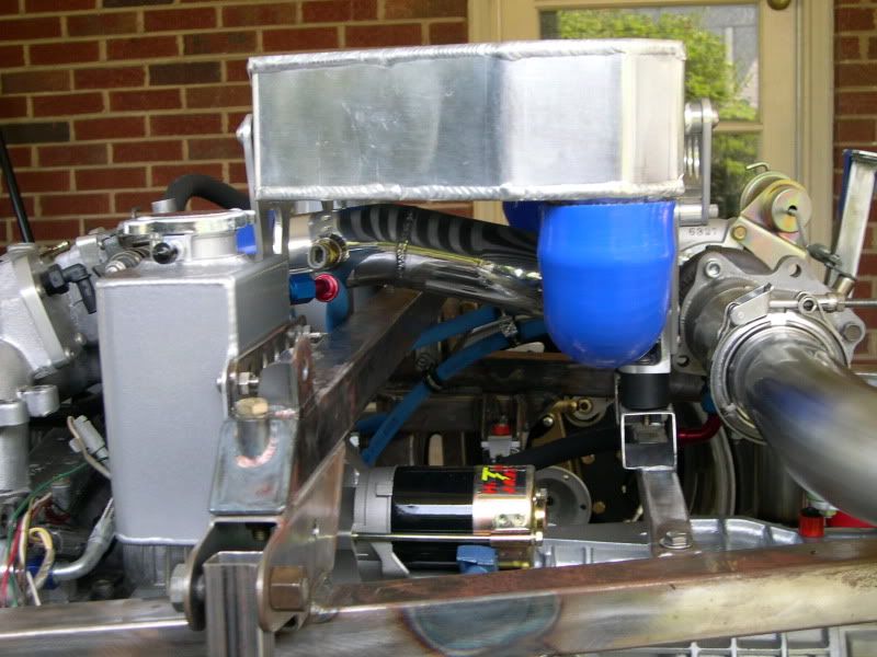
Now that I'm on the final stretch I'll detail some of the engine fitting - which has been only one part of this whole puzzle!

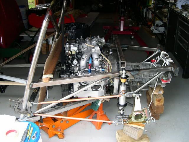
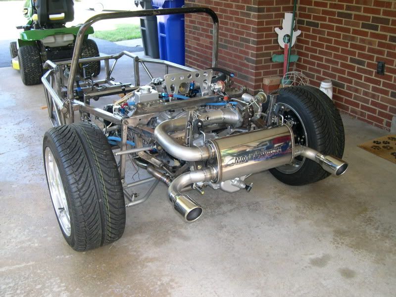
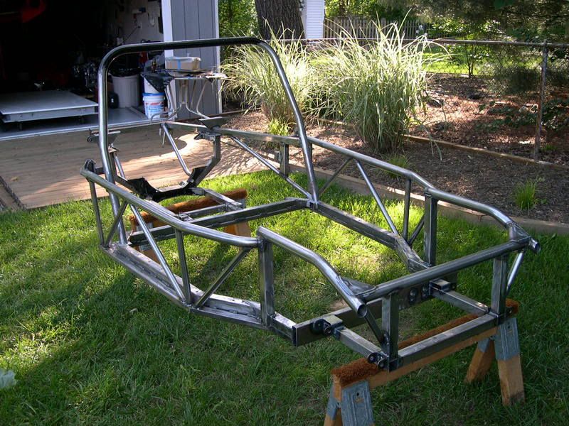
Here is a couple shots of the original GS chassis and layout - Corvair engine, VW swingaxle transaxle and torsion beam front end, all connected with a lightweight (as in about 80 lbs) tubular chassis and assembled with a monocoque fiberglass seat "tub" sheathed with the GT (or S1 "Manx" style body in these pics) fiberglass body. These cars were radical, and this was the late 1960's!

Image

Image

Image

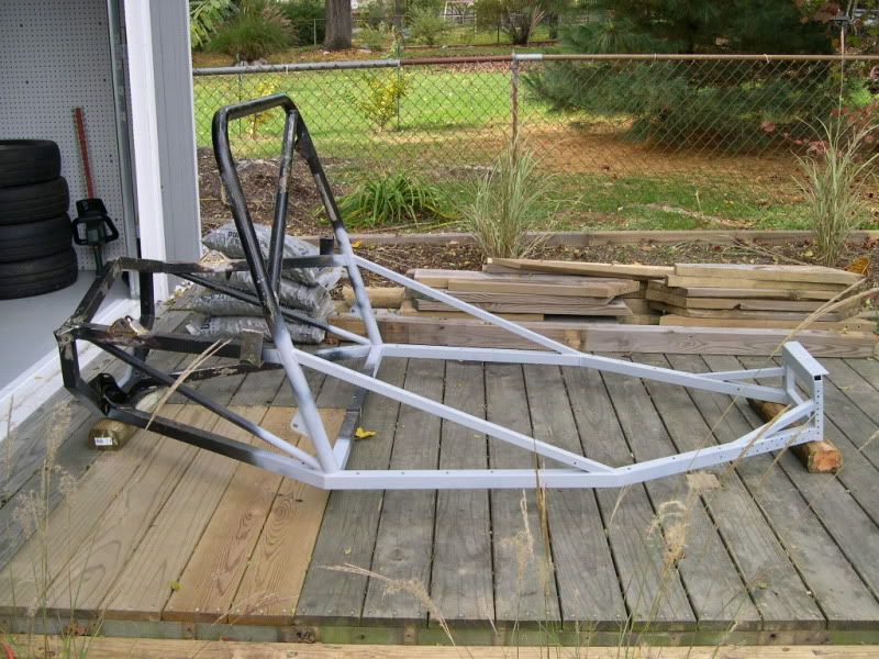
That's my original chassis in the first pic, which has since undergone some radical re-construction.

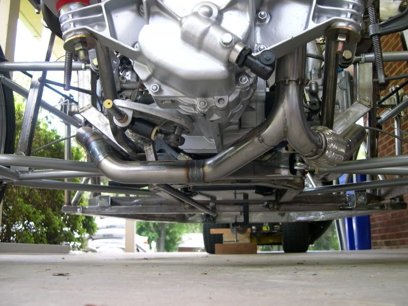
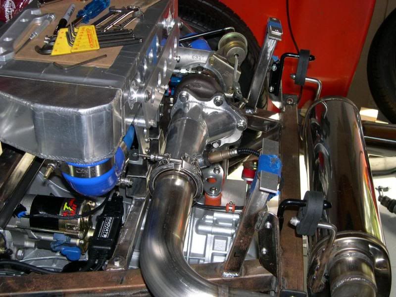
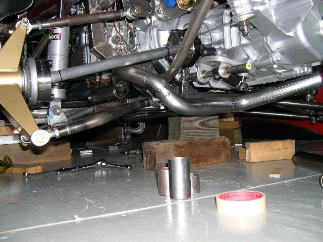
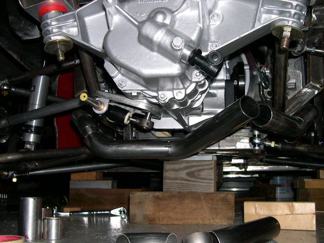
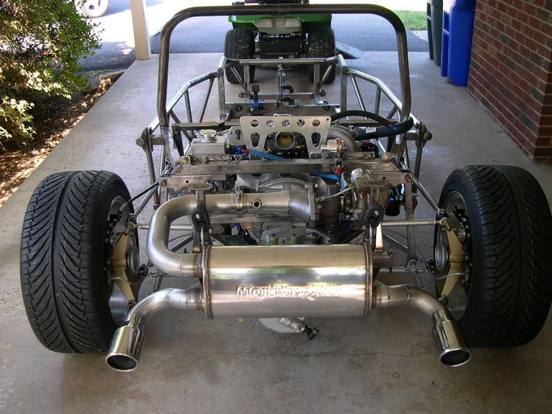
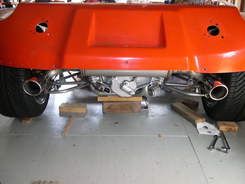
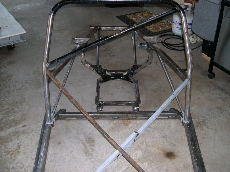
This is some of what I had to do to the back to accommodate the new rear suspension and EJ engine. Basically narrowing the lower frame supports to allow room for the exhaust to exit downward.

Image

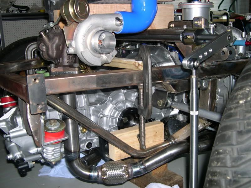
More chassis mods - I was no longer keeping the fiberglass tub and monocoque construction (I wanted "real" seats!) so more bracing and updating the front end to accept an a-arm suspension.

Image

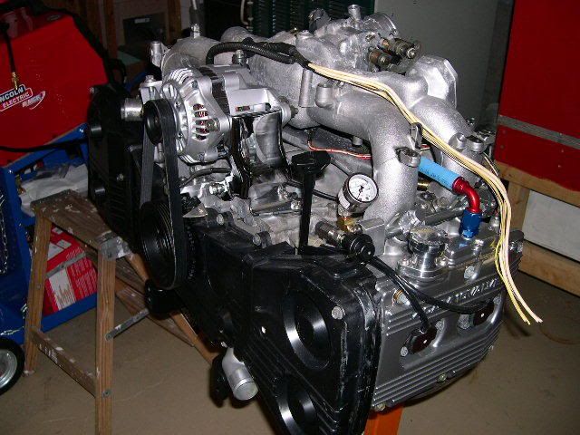
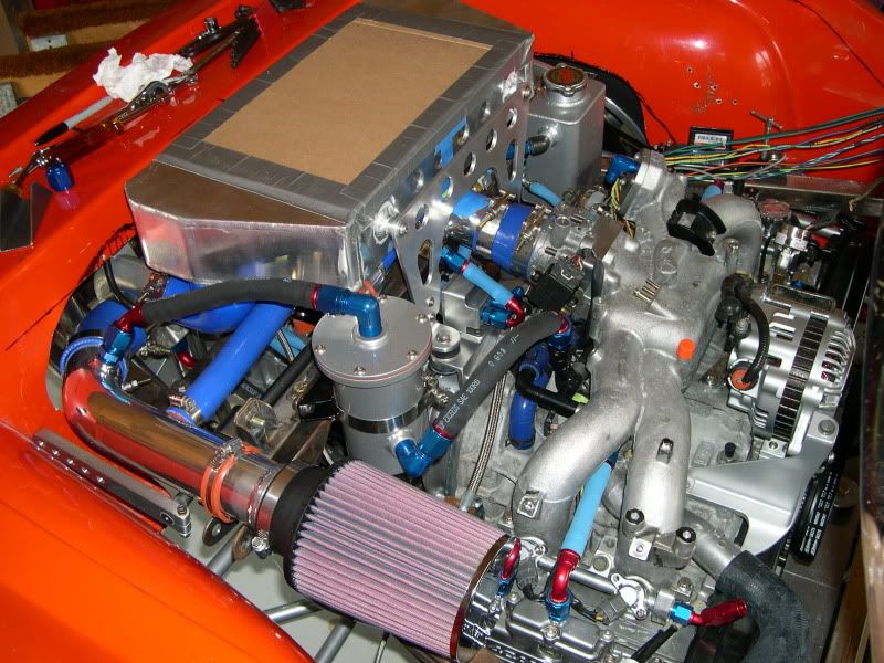
Onto the engine swap:

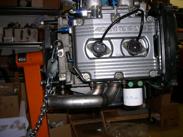
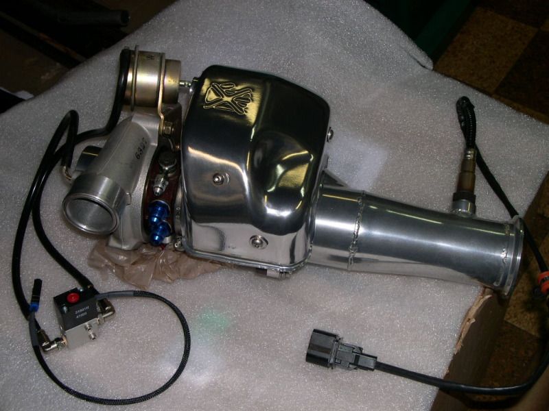
Just delivered - not too exciting to look at, just yet.....

Image

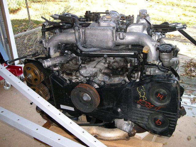
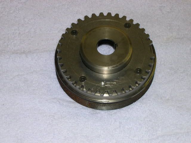
A diamond in the rough? :mrgreen:
User avatar
GS guy
Posts: 909
Joined: Wed Nov 06, 2002 12:01 am

Re: Deserter GS to Suby EJ20 Turbo

Post by GS guy »

EJ20 starting to look better now!

Image

Now some test fitting into the (early) chassis (with some early ideas on the rear suspension).

Image

Fast forward to these last "assembled" pics. This was my last full mock-up of the engine, trans and rear suspension before I pulled it all down for the front end work.
The mid-engine layout required a custom header and exhaust system - which had to be carefully snaked around the suspension and "stuff" around the back end. I located the WRX turbo up along side and just above the transaxle. The design of the exhaust had to incoporate the location of the intercooler as well - so it would all fit together and under an un-modified rear engine cover. It was "tight" to say the least!

Image

Image

Image

Image

I'll put up some more detailed pics of the Megasquirt installation in my next installment.

Cheers!
SuperRSi
Posts: 174
Joined: Mon May 31, 2004 12:10 pm

Re: Deserter GS to Suby EJ20 Turbo

Post by SuperRSi »

Very nice work!
User avatar
GS guy
Posts: 909
Joined: Wed Nov 06, 2002 12:01 am

Re: Deserter GS to Suby EJ20 Turbo

Post by GS guy »

Thanks Super RSI. I've been lurking and following your buggy build too, whenever I come across your posts.

Here's a little more detail about the Megasquirt set-up. Installing a MS2 V3.0 main board with Extra, and with the relay board. Ignition is set up for EDIS, using the original COPs firing wasted spark off the EDIS module. Keeping the Subaru coolant temp and VR sensors, adding the GM IAT and stepper motor idle control. It's been a while since I messed with any of this stuff so bear with me.
I decided to go with the EXTRA to add a boost control solenoid instead of just relying on the wastegate spring.

Adding the external 36-1 toothed timing wheel - I decided to locate the timing wheel in place of the AC belt on the damper. I machined the damper down to remove the AC pulley groves - but leave enough meat to support the "damper" rubber underneath. The damper outer portion was back-cut to not rub against the timing wheel which is attached to the inner hub. I made it bolt-on with a tight fit to the inner hub.

Image

Installing the modified damper required a little bit of trimming on the timing belt cover, but nothing extreme.

Using one of the OEM VR sensors I made an adapter to locate it above the timing wheel utilizing the original VR mounting hole to locate part of the support.

Image

And all installed.

Image

I did away with the original (and oversized) IAC valve and installed a remote valve from DIY Autyotune. It utilizes a GM stepper motor which the MS2 drives directly. I did a little clean-up machining and substituted my own fittings.

Image

Here it is installed on the car (underneath the throttle body).

Image

Feed hose comes from the intake tube between the intercooler and throttle body, and delives the bybass air into the original port opening in the intake with an adapter plate in place of the OEM IAC valve.

Image

At this point - I have no idea how I'll troubleshoot the operation of the IAC! It's pretty buried down there just above the bellhousing flange, and pretty much no way to see the valve operating as the engine warms up. I may have to rig up something temporary to just let it hang out in the open so I can physically see the pintle valve opening and closing during operation and engine running.

I fully enclosed the realy board with a different case.

Image

Here it is with the finished wiring harness to engine.

Image

And installed on the chassis in the drivers side pod, along with the MS ECU. I figured the side pod would be a good place to both keep it protected from the elements and away from the engine compartment heat. Plus, at this point real estate in the engine bay was getting very slim!

Image

I made the RB mount so that it can quickly flip down for general access and troubleshooting. I didn't like the idea of it sitting vertically like the ECU (with the relays and fuses "hanging there"), but with it mounted horizontal it was almost up under the side lip of the bodywork, so also not good for maintenance. Quick disconnect pins allow it to quickly flip down for easy access, and thumb screws mean no tools required to open it up for a look-see.

Here you can see the EDIS module mounted in the engine bay, right next to the (black) coolant overflow can.

Image

Innovate O2 electronics beneath the intercooler and sensor just aft of the turbo. An aluminum heat shield will be installed between the exhaust system and engine bay, and whatever other exhaust wrpping and insulating needed to keep the heat back there "under wraps".

Image

Last but not least, the boost control solenoid, over near the turbo compressor. Thought I had a pic but can't find one now - just imagine a little box with a small hose going in and coming out! :D
Ol'fogasaurus
Posts: 17758
Joined: Mon Nov 13, 2006 10:17 pm

Re: Deserter GS to Suby EJ20 Turbo

Post by Ol'fogasaurus »

Do you have plans for a side hit on the side as the body is not going to be of much help if you slide into a tree or a hard hit in a parking lot. Fiberglass is like that you know! :wink:

Lee
User avatar
GS guy
Posts: 909
Joined: Wed Nov 06, 2002 12:01 am

Re: Deserter GS to Suby EJ20 Turbo

Post by GS guy »

Ol'fogasaurus wrote:Do you have plans for a side hit on the side as the body is not going to be of much help if you slide into a tree or a hard hit in a parking lot. Fiberglass is like that you know! :wink:

Lee
Yea - I plan to stay out of the hospital as best I can!

The original GS (or GT) build plan could incorporate expanding foam filled side pods - mine used to be this way too. That provided some side protection plus added stiffness to the car. I needed the room inside the pods to house additional parts of the car - electronics, battery, oil cooler and a small amount of misc. storage.
User avatar
GS guy
Posts: 909
Joined: Wed Nov 06, 2002 12:01 am

Re: Deserter GS to Suby EJ20 Turbo

Post by GS guy »

A little more detail on the exhaust side of things.

As mentioned earlier I had to custom design the exhaust for this car. Some considerations directing the design were clearance below the motor for outlet stubs off the heads, positioning of the turbo, support of the turbo, clearance around the suspension and interfacing with the intercooler and intake system.

I decided to use the basic idea of the Outfront exhaust headers to simplify the overall design and layout. Likely it looses some efficiency with the unequal primary lengths, but trying to incoporate some kind of bundle of snakes curving back and around the suspension was too mind boggling to even consider! :shock: I love the looks of the symmetrical mid-engine sand buggy merged exhausts centering over the transaxle, and was initially thinking a turbo layout with turbo centered of the trans would be awesome - but in the reality trying to lay ouy and build such a system for this car wasn't going to happen.
The Outfront exhaust uses short primary outlet pipes coming off the heads which immediately merge into one pipe for each side. They're about as compact as you can get as far as hanging down below the engine and were a great start to building my system.

Image

They wound up pointing directly into my lower a-arms. Elbows were added to route around the a-arms and then past the axles. I'm running around 5" of rear wheel travel in the back so full axle articulation had to be taken into account. The drivers side then tucks under the trans and merges with the passenger side where it turns vertical to run up to the turbo. I used another Outfront flange to mount the WRX TD04 turbo. As it worked out, I didn't have a whole lot of options on where I could locate the turbo. I wanted it up higher than the engine for good drainage, and it needed to be positioned to feed into the roughly planned intercooler lcoation. When you're dealing with 2.5" (intake) tubing it quickly becomes apparent where thing can and can't go to accommodate the bends and clearances required. I also decided to add in a flex section on the passenger side to hopefully ward off cracking with heat-growth of the system.
Another aspect I considered critical was how the welding of the different sections would affect the final shape of the exhaust. The placement of the turbo didn't leave much fudge room, it had to wind up exactly where it was planned. I wasn't doing the final welding, just tacking with my mig and letting Bills Metals down the road handle the final welds with his expert tig hand. It would have been much easlier to tack the whole exhaust together then let Bill finish it up, but in consideration of things possibly moving from welding, I only tacked then fully welded sections of the exhaust together at a time, working from the heads back fitting the new sections one at a time. This worked great but time consuming (lots of trips back and forth to Bills!) and located the turbo exactly where I wanted it.

Image

Image

Image

Now the turbo was positioned, and sitting well aft of the engine. Couldn't rely on the exhaust to support it, but knowing the whole system will move as it grows and contracts - how to get a "flexible" support that can handle all the heat? And what to mount it to? I decided it needed to be mounted to the engine/trans combo and move with them, opposed to the chassis. An inverted L-bracket off the trans tailhousing provided a mounting point, and high durometer silicone based bushings off that to connect to a flat steel tab connecting to the turbo. I think this should work pretty well. (Note: the pic shows the mock-up tab, I later fitted a thicker steel tab - same shape - don't have any current pics of the final tab.)

Image

I also re-did all the plumbing fittings off the turbo to accept AN fittings. The coolant lines take a standard carb fitting and I used the OEM bajno bolt with the built in restrictor for the oil feed. The drain took a custom adapter for 1/2"npt to 10AN hose.

Image

Coming off the turbo is another neat custom piece. I wanted something similar to the "bellmouth" downpipes for good flow out of the turbo and wastegate, but needed a more universal fit exiting straight out - not curving down. An outfit called ZTS Speed made this part and did a beautiful job. They were pricing these at only $100, but I guess the demand just wasn't there and they're no longer around.

Image

Image

It exits at 3", to which I fitted a collector reducer to bringing it down to 2.5" for the rest of the exhaust. Also fitted the O2 sensor in this section and a SS band clamp. From there I used all SS piping and parts back to a Magnaflow 1-in 2-out muffler and Vericous Motorsports exhaust tips.

Image

These exit just underneath the bodywork - and hopefuly will give a mellow (and not too loud) but powerful sound!

Image

Finally, after all the fitting and assembly, I had the steel parts ceramic coated for longevity and hopefully help keep the heat inside!

Image

More recently I was trying to decide what to do about the exhaust housing heat. Originally thinking about a blanket or aftermarket metal shield, but decided against that in favor of an OEM style heat shield. This had to be modified to work around the "down-pipe" and a little trimming here and there, and then had it ceramic coated. I really like how this has a clean "fitted" look.

Image

I may have to wrap some of the exhaust depending how much heat it radiates to surrounding areas? Have to play that by ear once it's running.


Next up I'll get into the intake system.
User avatar
GS guy
Posts: 909
Joined: Wed Nov 06, 2002 12:01 am

Re: Deserter GS to Suby EJ20 Turbo

Post by GS guy »

Here are a few details on the intake system. As you guys know - the intake is intimately tied into the exhaust with a turbo. In my case, both had to basically be designed and fabricated simultaneously. A LOT of plumbing has to all work and fit together in harmony, especially in the generally tight confines of the engine compartment.
I found a suitable intercooler on ebay, only had to modify the inlet port location to get the IC where I wanted it.

Image

This gave me a short path from turbo compressor to IC. The compromise was a little longer path out of the IC into the intake. Also this path needed to run under the IC to get back to the engine with minimized large radius bends. My intake tubes are all 2.5", same as the post-turbo exhaust.

Image

Image

Here's a mock-up of the IC to throttle body tube in PVC - to see how it would fit and work in full scale:

Image

My original idea was to try and duct airflow up under the IC, pushing air up through it and out the top of the engine cover. Once I got the intake tube completed, along with other items in place related to the engine and suspension there was very little room left for ductwork or creating a plenum under the IC.
Plan B: duct into a plenum on top of the IC, down and out the bottom. I am fashioning air inlets in my buggy side pods to provide this air (similar to the Manxter), plus as supply air to my remote oil cooler. More room to duct air over the top of the engine and IC, vs below (but more clutter on top of the engine :( ). This means it will be flowing right onto the intake tube underneath - so might have to insulate it? Or not....

I selected a Samco 1" blow-off valve, with silicone hoses connecting it to the intake and air cleaner tubes. Had to make a custom mount for the Samco valve as they didn't design in any integral mounting points for it!

Image

IC to TB tube completed, with Samco BOV:

Image

And here's how it mounts under the IC (BOV on the opposite side, can't be seen in this view). This gave about the best and most direct route from IC to throttle body (still a lot of right angle turns in my intake system though):

Image

Another pesky detail that popped up - I couldn't fit the intake in place with the odd angle of the throttle body coming off the OEM intake. It would have hit the underside of the intercooler - space was starting to get tight! Found this neat little throttle body "wedge" from a Subaru-Vanagon site, well sort of. I got the wedge kit, which normally would make the TB sit horizontal - about parallel with the crank centerline. However, this put my intake running directly into a chassis brace just behind the engine! I was able to get this onto a milling machine and basically "half" the angle of the wedge. This positioned the TB perfectly but a bit of a pain to do!

Image

Finally the air cleaner inlet to the turbo. Another 2.5" aluminum elbow worked pretty well to position the filter up closer to the front of the engine and away from the exhaust heat. I machined an adapter collar to fit a K&N filter, along with ports for the BOV and crankcase vent system.

Image

I may eventually build a cold air box around the filter? Not exactly sure where I'd get the cool air from as I really don't want it coming through the engine lid - with intake noise right behind your head! Maybe just pick it up down low from the engine bay, should be some high pressure air down there to tap into.

Another little (aggrivating!) detail I ran across while working on this system - finding universal silicon hoses that fit the WRX turbo! WTF? Both compressor openings on that thing are just a little too big or too small to fit standard hose sizes! I eventually decided to Make the openings fit standard hardware - by machining spacer sleeves that fit over both the inlet and outlet sides and red lock-tite them in place. What a pain, but it worked - here's the compressor outlet sleeve in place (intake side was done similar):
Image

Sheesh! :roll:
User avatar
CBDZ
Posts: 183
Joined: Mon Jun 01, 2009 9:22 am

Re: Deserter GS to Suby EJ20 Turbo

Post by CBDZ »

WOW!!!

Super Impressive.
My Car Details:
Fiberglass Buggy on 1973 Chassis.
1904 cc
Megasquirt (MS1 with 3.57 board) Fuel Injection: German Intake Plenum, CB Performance End-Castings, Ford Escort Throttle Body with custom Adapter, MS controls Wasted Spark Coil Pack
User avatar
GS guy
Posts: 909
Joined: Wed Nov 06, 2002 12:01 am

Re: Deserter GS to Suby EJ20 Turbo

Post by GS guy »

Thanks CBDZ.

It's like a kit car - except you have to design and build the whole kit - from scratch! No instructions! :D
User avatar
RonW
Posts: 544
Joined: Tue Jan 03, 2006 8:31 am

Re: Deserter GS to Suby EJ20 Turbo

Post by RonW »

great build, love watching it come together. which turbo is it?
Steve Arndt
Posts: 7404
Joined: Sat Mar 10, 2001 12:01 am

Re: Deserter GS to Suby EJ20 Turbo

Post by Steve Arndt »

Nice fab work!
User avatar
GS guy
Posts: 909
Joined: Wed Nov 06, 2002 12:01 am

Re: Deserter GS to Suby EJ20 Turbo

Post by GS guy »

Thanks guys,

Ron, the turbo is a stock WRX TDO4. I'll have to see how this one runs before deciding whether to step up to something bigger and more boost. The nice thing is there are several larger sized models that have the same inlet/outlet exhaust flange pattern as the stock turbo - so easy to swap. This one should support a good 10lbs.
User avatar
GS guy
Posts: 909
Joined: Wed Nov 06, 2002 12:01 am

Re: Deserter GS to Suby EJ20 Turbo

Post by GS guy »

Here's some detail on the PCV and engine vent system.
I've seen some buggy engines that use simple plug-on K&N filters on top of the valve covers, and who knows what for the main crankcase vent? Last thing I want was oil weeping filters all over! The plan was to maintain a "factory like" PCV system, but get rid of the ugly black plastic PVC vent pipe on top of the engine. Also, little availability for all the short molded hoses with tight compound bends - and mine were hard as rock.

I first studied the OEM PCV layout to see what I could come up with:

Image

Doesn't look all that complicated - but something interesting happens if you follow the general flow path. During non-boost conditions, it seems normal flow is from the air cleaner into the valve covers, through the engine and out the main discharge hose (typical PCV flow in most engines), finally through a 2nd tube and into the PCV valve to intake manifold. Note that the stock system has a small restrictor in-line in the higher tube (just before the T to the main crankcase vent connection) that would otherwise appear to bypass the lower "through the engine" system and go straight to the PCV valve from the main air intake. This must bias the airflow through the engine instead of bypassing - as it looks like it would in the pic above.

Here is my modified layout:

Image

It mimics the OEM design, except with just one air inlet and all the intake air must pass through a sealed catch can. Note the restrictor that biases the flow through the engine like stock. I copied the ID of the factory restrictor for my custom set-up.

So what happens under boost? As near as I can tell the crankcase is under pressure so I believe both the valve covers and main vent at the back of the motor act as outlet vents. Flow is reversed out the valve covers and with PCV closed, the only way out is back out into the main air inlet tube. It probably sees a little vacuum there so would get drawn into the engine via the turbo and intake tract. The catch can is there to "trap" any oil vapor coming out of the engine under boost, an attept to keep it out of the intake system.

This takes a little while to study and figure out - especially since the physical shape and connection arrangement on the engine looks very little like the diagrams! Sort of like electrical diagrams - you have to carefully study the flow paths to see what is happening and what goes where.

Here was the stock connection at the back of my engine - coming up off the main crankcase vent:

Image

I call that the F pipe, the left side going to the PCV valve, right to crankcase vent and crossover tube to the valve covers. The connections to the intake tube came off the crossover pipe to the valve covers.

Here is the "new and improved" home depot version. :D
I kept the F pipe and re-routed the valve cover crossover tube, with a restrictor:

Image

Image

Mock-up install:

Image

Finally painted and finished:

Image

Image

So the pipe sticking up is the main air inlet to the system. It routes through the catch can and from there into the main intake tube.

Heres another "home brewed" idea - the catch can I came up with. Engine vapors come in through the side inlet, have to travel down to the bottom of the can, pass through the center tube baffle up through the middle, then transfer from the center back out to the outer edges, and finally through some fuel tank open cell foam to get to the opening at the top.

During fabrication and setting up for welding of the fittings, with internal baffle sitting next to it:

Image

And final hose routing:

Image

I wanted to incoporate some kind of automatic drain where I currently have a shut-off valve in the bottom of the can, but don't have a good drain back point? The only thing near by is the turbo oil drain and not sure it would make a good catch can drain too. For now I'll just keep and eye on the oil level inside and see if any really accumulates or not.
Steve Arndt
Posts: 7404
Joined: Sat Mar 10, 2001 12:01 am

Re: Deserter GS to Suby EJ20 Turbo

Post by Steve Arndt »

The vent flow directions flow will be conditional on your ring seal, RPMs, boost, and engine health.

The general idea is force air into the valve covers, pull vacuum on the case, into the engine intake. When blowby (positive crank case pressure) starts, it generally vents to atm.

Having a catch can and oil separator between the crank case and vacuum source into the intake always helps.

Lots of people do away with the pcv valve, and run a constant bleed restrictor (to prevent a big vacuum leak to the intake plenum).
Post Reply