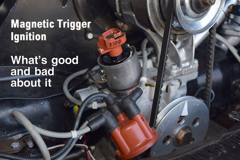
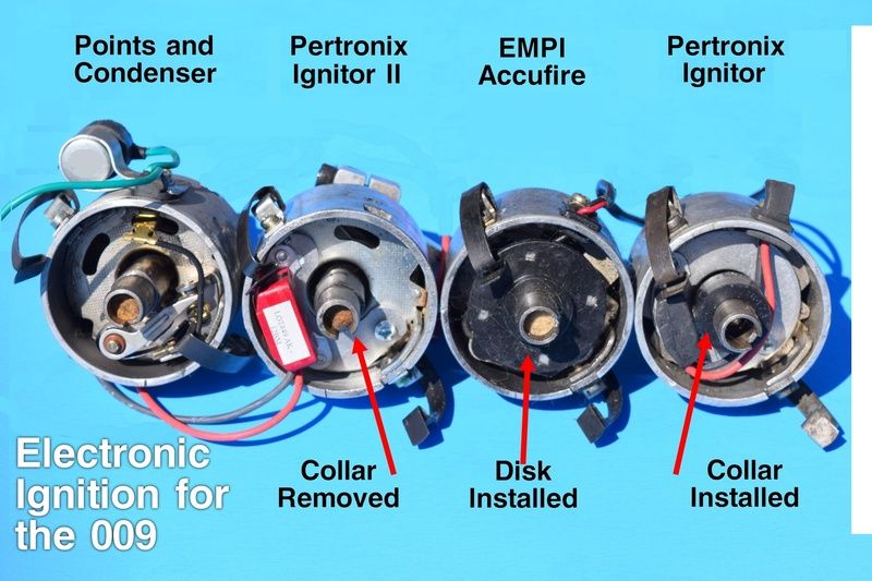
Above: EMPI Accu-Fire in a 009 distributor. The Ignitor, Accu-Fire, and Compu-Fire are all compatible with Bosch rev-limiting rotors.
Ignition breaker points as we know them originated with the Kettering system, which was introduced in the 1910 Cadillac. That's a long time ago. The Ignitor II a step up over the original Ignitor and clones Accu-Fire and Compu-Fire. It can calculate varying voltage needs and tune the dwell time on the go.
First, a very short refresher guide in three steps to the Kettering breaker points system.
https://www.youtube.com/watch?v=W94iksaQwUo
(1) The ignition coil is fed current from the battery into its positive terminal. The current is conducted through internal copper wiring in primary and secondary windings, boosting the voltage from 12 vdc up to 30,000 vdc or more, depending on designed coil output.
(2) The current in the coil is ready to go somewhere. The ignition breaker points are a spring loaded switch opened by a spinning cam inside the distributor. A rubbing block on the points contacts the cam to push open the points, and requires a touch of lube to slow down its wear. When the points are closed, the rising current in the coil shoots from the coil to the central middle wire in the distributor cap to the center of a rotor cap inside the distributor, atop the cam shaft. The transfer of current from the ignition coil to the rotor cap discharges the ignition coil.
(3) The electrical condenser (aka capacitor) is a small cannister wired between the negative pole of the ignition coil and the breaker points. It acts as a cushion or regulating device to protect the points from having to deal with the full energy directed at them. Without a condenser, the points would quickly weld together. Tungsten steel, A very durable metal, is used by Bosch for the breaker points contacts.
All this is a complex process vulnerable to wear, misadjustment, and moving mechanical parts.
Hall Effect (optical) vs Magtrigger
Magnetic-trigger in this report is different to the classic "Hall Effect" (discovered by Edwin Hall in 1879) is an optical-trigger ignition which uses a photocell shining through holes in a revolving wheel. A photoelectric eye aligned with the wheel sees the light and activates the signal to fire. There have been Hall-Effect ignitio modules, but they are rare now, in favor of Magnetic trigger.
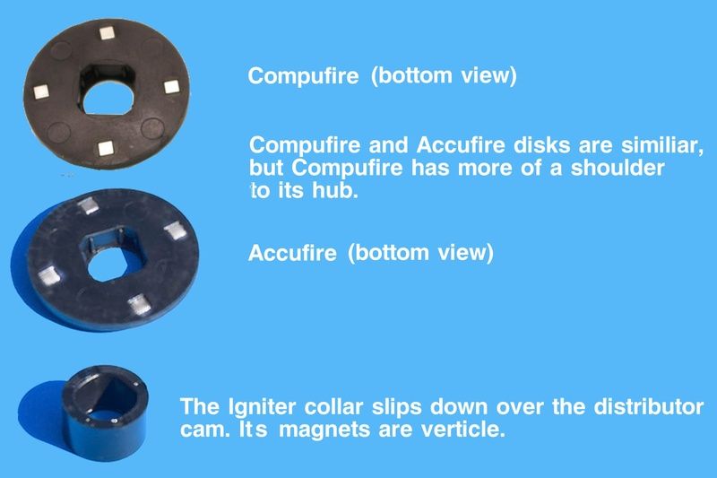
Magnetic trigger ignition modules, such as the Pertronix Igniter or EMPI Accu-Fire, use a disk or sleeve embedded with cobalt magnets rotating on the distributor cam to make a transistor in the module switch and cause the ignition coil to discharge. No condenser is necessary.
We are focusing just on the least expensive magnetic trigger systems here, because more of them are in use than the more complex systems, especially if you count the high-dollar full-featured electronic ignitions such as MSD.
1972: the "solid state" ignition era begins
Solid state was a popular advertising buzzword as radio and TV chassis became transistorized. It meant no vacuum tubes. No warm-up delay. Instant on! When it became to be applied to automotive ignitions, it meant no mechanical breaker points and no condenser.
In 1972, Chrysler was the first auto maker to introduce breakerless ignition, using the magnetic trigger. It also had its own ECU (engine control unit), a refinement the basic Accu-Fire, Compu-Fire, and Pertronix Ignitor we're examining here lack, except in the case of the Ignitor II, which has a built-in micro controller that adjusts dwell predictively based on voltage supply.
The Chrysler solid state ignition systems were modular, meaning able to be replaced as a unit, and from that we get our first definition of an ignition module. They were also backwards compatible, and people with older Chrysler ignition could have their points and condenser replaced with one of the new, high-efficiency modules.
About the same time, Per-Lux (which was to become Pertronix) began manufacturing breakerless ignition modules for industrial vehicles such as fork lifts. From there, Pertronix expanded to automotive use. By the late-1990's magnetic trigger ignition modules were becoming available to the air-cooled VW crowd.
Dwell time is how long the points stay closed, as expressed in degrees out of a 360°circle. For the 009 distributor, dwell is 47° deg. +/- 3°. While the points are closed, the coil is discharging power to the rotor and hence on to the spark plug. We want the longest dwell time possible to burn as much air/fuel mixture as we can and get the most spark plug firing power. The right dwell is provided by setting the point gap correctly. Too little or too much gap (i.e., dwell) will rob power.
The original Pertronix Ignitor, and its clones the Accu-Fire and Compu-Fire, give us consistent maximum dwell times. No rubbing blocks to wear and change dwell, no opportunity to misadjust the points. The Pertronix Ignitor II, as mentioned earlier, can adjust dwell by anticipating weaker voltage caused by very high RPM and making the system fire earlier in the cycle to get more power.
As soon as the points reopen, the coil begins to recharge itself (recycle) in prep for firing the next plug. "Voltage rise time" comes into full effect here. The coil must recycle itself in time for the next firing. The faster the RPM's, the less rise time we have. At 7000 RPM a coil is being forced to fire 600 times a second.
An indication of fast rise time capability is in the "turns ratio," of an ignition coil. We call them "coils" because internally they have copper wire wrapped around a central magnetic core. The wrappings are expressed as a ratio between the number of secondary turns and the number of primary turns.
The Black, Blue, and Red Ones From Bosch
We associate the Blue coil with VW and Porsche, but it was also a favorite of the European 4-cyl DOHC Ford racing engines, to include 16-valve Cosworths. Coupled with capacitive discharge ignition, it powered the mighty 917's.
The Bosch Black, Blue, and Red coils reflect Germanic thinking, similar to Porsche's designation of its 356 sports car. You had a choice of the Normal, the Super, and finally, the Super 90. Each model reflected a class of performance. American hot rodders could run anything on the street they could get a tag for, but in Germany, if you upgraded a car's engine, you legally had to also upgrade the brakes that went with that engine. The Black coil was for 4 cyl engines, the Blue for 6 cyls, and the Red for 8 cyls.
The standard Bosch black coil has a turns ratio of 100:1 and a max output of 13.5 KV. The Blue coil has a turns ratio of 150:1 It can deliver 17.5 KV when fully cycled up. This is good for properly maintained ignition systems at medium to high (3000 to 7000) RPM where more firing voltage is needed to jump the spark gap in a dense air/fuel cylinder mixture. At high RPM, even when not fully recharged, it delivers a stronger spark than the Bosch black coil. The Red coil can produce 25 KV and has a turns ratio of 200:1.
The Blue coil is not a true racing coil if all you're doing is judging by max possible output, but with points, it is a good upper midrange performance coil. It consistently delivers strong ignition current up to 17.5 KV volts with decent recycle time. There are aftermarket coils that can produce 40 KV volts, better for igniting rich fuel mixtures in high compression engines at 6000 RPM and up. The compressed fuel/air mixture is an insulator and it takes current to jump the gap.
Even though a coil may be physically able to deliver 40 KV volts, such high output is rare. What happens is that the voltage will only rise as high as it takes for the plug gap to fire. The voltage required might be as low as 3,000 volts or as high as 30,000 volts. An ignition advertisement-to-truth fact is the maximum coil voltage is NOT what is sent to the plugs. The maximum is a reserve. Spark plugs "demand" whatever voltage it requires to create an arc across the plug gap.
Having an extremely high voltage coil may not always be an asset. If a plug has not fired by 30,000 (which can jump an air gap of about an inch), the connection to that plug may have been lost by melting and shorting ignition boots, cracked caps, and wires created by a failing plug and enough coil voltage to keep on trying to fire it by brute force.
Point Bounce
As RPM's increase, the little spring that closes the points gets more and more of a workout until it reaches its own limits, and you get "point bounce." You feel it as high RPM misfires.
Savvy VW racers found out which Porsche points springs fit what VW breaker sets, and changed over, expecting the Porsche spring might be better at redline.
The Hall-effect or magnetic trigger system, of course, has no point bounce.
Marketing Exaggerations
Early on, ads for the simple mag-trigger modules often told outright lies about delivering more power to the plugs. The truth was, you did get more power, as opposed to what you got during a fit of point bounce. And dwell was always spot-on, which did mean more power as opposed to your points being out of adjustment.
Solid-state ignition points replacement modules were not, and are not voltage boosters.
Magnetic trigger Ignition Modules: Threat or Menace?
You sometimes hear or read about mag-trigger systems running then mysteriously quitting altogether, and maybe even smoking (then quitting) or apparently unprovoked, bursting into flame.
You were probably warned at some time in your life not to leave the ignition switch on without the engine running. In a breaker points system, if the points happened to be closed with the ignition on, the metal contact surfaces of the points tended to arc together and transfer metal (think spotweld) from one contact to the other.
Most of us knew that. But something we didn't all know was direct battery current to the coil positive could overheat oil-filled coils to explosion and fire. The oil boils, ruptures the case, and can catch fire. Epoxy-filled coils are no less prone to expanding and splitting if overheated, but don't usually catch on fire.
Leaving the ignition on with a mag-trigger system has all the kamakazi-coil symptoms of a breaker points system with death of the solid-state ignition module thrown in. They can't take the heat.
The solid-state ignition modules are encased in hard epoxy to seal them against moisture, resist vibration, and keep curious mechanics away from the actual electronics inside. The epoxy is also (to a point) a great insulator. But short-circuited ignition wiring can keep the module hot after you've parked the car, turned off the ignition, and gone indoors to take a nap. The epoxy finally overheats, melts, and catches fire. This is not common but it has been reported.
Low Voltage
A more common problem is you install your new module kit and the car runs great. But later in the day, downtown between errands, you get no start. After much checking of everything you can, the car starts up again just fine. This is a solid-state ignition module problem caused by low voltage to the module.
Low voltage itself is caused by high resistance caused by overheated wires and connections. It is the primary reason VW starters, bolted directly to the very hot transaxle case, sometimes refuse to even spin over. Not enough voltage or amperage. The solid-state module needs a consistent 12vdc, not 10 volts. This low voltage condition would never bother points. And it can happen without the tell-tale hot starter, just a bad ignition key circuit you didn't know you had while you ran points.
Then there is the total and inexplicable failure, Electronics being what they are, they are prone to instantaneous failure. Think of a light bulb burning out. This is more in the "It just died while setting in the driveway overnight" category. In the solid-state, moment of shutdown or start up, an imperfect transistor bit the dust.
Mechanical distributor trouble
As great a development over the points and condenser system as the transistor Hall effect is, there are weaknesses in it. Installing a mag-trigger module in a mechanical distributor subjects the purity of the Hall-effect itself to mechanical imperfections such as sloppy clearances, and poor build quality.
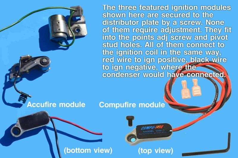
Distributor shafts turning in worn bushings or with improperly installed magnet disks degrade the trigger signal as the rotating cobalt magnets wobble out of orbit and pass too far away from the sensor. "Too far" here literally means just thousands of an inch.
Electromagnetic Ignition Jamming
Magnetic trigger ignition is sensitive. For instance, it is susceptible to electromagnetic fields. Pertronix openly warns against the use of solid core ignition wires, which radiate terrific RFI (radio frequency energy) and electromagnetic pulse can cause the magnetic trigger to temporarily malfunction.
This RFI/EMP vulnerability also means you might experience misfires or even have the engine quit outright as you drive over railroad tracks that are beside or under high-tension power lines. This was also a problem with original electronic Bosch D-Jet systems on Type 3's if the aluminum shielding protecting the computer was missing.
Bad grounds
Magnetic trigger ignition's most common problem is poor grounding. An unstable battery ground makes the system attempt to overcome the situation by trying to increase voltage to overcome the resistance. That kills the modules. Personal experience talking on this one.
Ignition modules that have worked loose (set screw loosening) inside the distributor also break grounding as well as possibly beating up the module itself if it's the sort under the flat disk. This has happened to me too. Consider a tiny drop of Locktite Green on the module's hold-down screw.
Out-of-phase Ignition Failure
Something to really mystify veteran breaker points people is how an ignition module can fail and begin firing out of time with the rotor cap passing the internal distributor cap contacts and then firing. That means no spark to the plugs. Imagine in a points system that the rotor cap had somehow twisted inside the distributor so that the spark it delivers occurs between the spark plug pickups.
This can happen if the plastic disk or sleeve holding the cobalt magnets has been damaged somehow and is itself no longer aligned, but can also be electrical failure inside the pickup module. Usually, a malfunctiong module won't work at all, but that doesn't stop the evil glitch gremlins from getting inventive.
Picking The Right Ignition Coil
[URL=http://s258.photobucket.com/user/fjcamper/media/Pertronix%20coil%20chart_zpsm3g6sxbw.png.html]
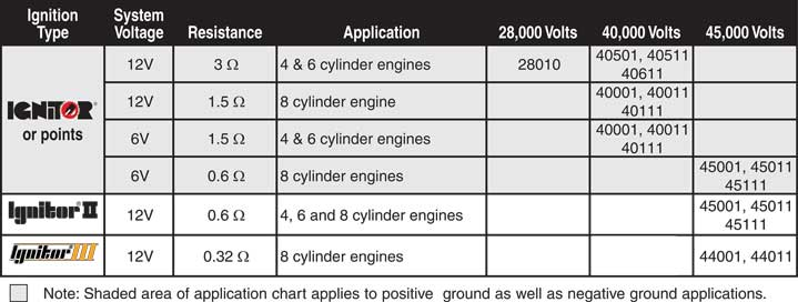
The Mag-trigger system requires regulated power, just like carburetors require fuel pressure regulators. The voltage and amperage of any Hall-effect system is determined by the manufacturer, who tries to take into account what type of ignition coil will be used with it.
Because we're focusing on the basic mag-trigger modules, the Pertronix Ignitor and Ignitor II and clones Accu-Fire and Compu-Fire, most of you will be glad to know all the modules covered in this post work with the Bosch Black and Blue coils, and of course, the Pertronix coils that match up with Pertronix Ignitor.
At this point, things get blurry as we have many ignition module and coil specs, with ballast resistor variables, to chose from.
Ballast Resistors (internal and external)
All ignition coils made for points system have a ballast resistor, either inside or outside the coil itself. The resistors protect the points.
You don't want a spark to jump across the points gap when they are open. Sparks make four to five THOUSAND degrees F., so excess voltage to the points, pushed by a more powerful than required coil, can burn the breaker points.
Right now you should get wary. It seems like advertising has told us everything done to improve our ignition systems increases voltage, and now we want to add resistances to limit that voltage? Yes. And it's been true since the evolution of ignition coils as they all began to be similar since the 1920's.
To reduce the amount of voltage being switched by the points, it became standard practice to use a resistor so the points would only have to conduct about 9-volts instead of the 14.4 volts that an alternator should be delivering.
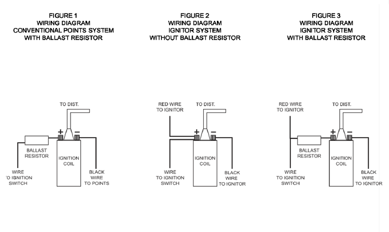
Ballast resistors can come built-in (such as the Blue coil) or external (such as the Red coil). All you have to do is follow the Pertronix instructions on how to hook up an Ignitor to the coil and resistor.
Checking Yourself For Which Kind of Resistor System You Have
To find out for sure, use a multimeter to check the voltage on the positive wire of the coil with the ignition on. About 9v means you have a ballast, about 12v means you don't.
FJC