I'm sure it does but I just wanted you to explain the math behind the decodePiledriver wrote:Paul, I assure you it does work, and for fully sequential operation, one sensor, one wheel at cam speed.
Redline Weber has been selling that 24-1 setup for awhile, for a variety of engines.
It wouldn't work well on many V6/V8s or any motor where the distributor gets driven via the oil pump via a long sequence of drive chains etc, but on an ACVW is all direct drive gears, unless you have slop in the distributor or a dorked up brass gear it seems very stable.
To try it, I made up a 16-1 using a modified mallory unilite rotor/shutter wheel setup, then later made a 36-1 in a 009 using a home brew sensor setup ($7 commercial sensor, home brew packaging)
It saves an input as well, (I/O is in short supply on MS2-extra compared to possible features)
cam and crank trigger combo inside a distributor (megasquirt
-
Paul H

- Posts: 744
- Joined: Wed Jan 22, 2003 12:01 am
Re: cam and crank trigger combo inside a distributor (megasq
-
Piledriver

- Moderator
- Posts: 22520
- Joined: Sat Feb 16, 2002 12:01 am
Re: cam and crank trigger combo inside a distributor (megasq
Sadly I suck at math, or I would have become an EE...Paul H wrote:I'm sure it does but I just wanted you to explain the math behind the decodePiledriver wrote:Paul, I assure you it does work, and for fully sequential operation, one sensor, one wheel at cam speed.
Redline Weber has been selling that 24-1 setup for awhile, for a variety of engines.
It wouldn't work well on many V6/V8s or any motor where the distributor gets driven via the oil pump via a long sequence of drive chains etc, but on an ACVW is all direct drive gears, unless you have slop in the distributor or a dorked up brass gear it seems very stable.
To try it, I made up a 16-1 using a modified mallory unilite rotor/shutter wheel setup, then later made a 36-1 in a 009 using a home brew sensor setup ($7 commercial sensor, home brew packaging)
It saves an input as well, (I/O is in short supply on MS2-extra compared to possible features)
...for example, I still consider "management" to be a 4 letter word.
If you are really curious how it works in detail, the MS2-extra and older versions (1 rev back) of the ms3 code are downloadable for all to see... std vanilla C code.
Addendum to Newtons first law:
zero vehicles on jackstands, square gets a fresh 090 and 1911, cabby gets a blower.
EZ3.6 Vanagon after that.(mounted, needs everything finished) then Creamsicle.
zero vehicles on jackstands, square gets a fresh 090 and 1911, cabby gets a blower.
EZ3.6 Vanagon after that.(mounted, needs everything finished) then Creamsicle.
-
Paul H
- Posts: 744
- Joined: Wed Jan 22, 2003 12:01 am
Re: cam and crank trigger combo inside a distributor (megasq
I'll give the download a miss and I'll go and hang some sky hooks and mix up some tartan paintPiledriver wrote:Sadly I suck at math, or I would have become an EE...Paul H wrote:I'm sure it does but I just wanted you to explain the math behind the decodePiledriver wrote:Paul, I assure you it does work, and for fully sequential operation, one sensor, one wheel at cam speed.
Redline Weber has been selling that 24-1 setup for awhile, for a variety of engines.
It wouldn't work well on many V6/V8s or any motor where the distributor gets driven via the oil pump via a long sequence of drive chains etc, but on an ACVW is all direct drive gears, unless you have slop in the distributor or a dorked up brass gear it seems very stable.
To try it, I made up a 16-1 using a modified mallory unilite rotor/shutter wheel setup, then later made a 36-1 in a 009 using a home brew sensor setup ($7 commercial sensor, home brew packaging)
It saves an input as well, (I/O is in short supply on MS2-extra compared to possible features)
...for example, I still consider "management" to be a 4 letter word.
If you are really curious how it works in detail, the MS2-extra and older versions (1 rev back) of the ms3 code are downloadable for all to see... std vanilla C code.
-
Redline Weber
Cam and crank trigger combo inside a distributor 48-2
MATHWORKS : Another SIMPLE statement, a RULE, is what even divider can be used for a Crankshaft Target.
THINK : A "gear down" TW = 2X of the crankshaft tooth count.
Thus we ALSO make, sold for many years, a CAS TW of 48-2 (24 crankshaft) count.
The MATH states fifteen degrees for a V-8 engine each tooth.
NOW when I READ about a 36-1/2 "gear down" I am amused GREATLY. (18@crank)
MATH=4 divided by 18 is NOT even close to being an even count for a VW-Type.
The next GREAT ERROR is about cam belt, oil drive, valve train harmonics deflection as being intense.
TRUE, the crankshaft is still the best location, in the center is BEST for TW location.
THOUGH the truth when observer, not GUESSED ABOUT, IS that the "high res" CAS will AVERAGE its general position filtering out these vibrations.
The Gear Down single engine position encoder is a viable method when understood.
Lance
-
Paul H
- Posts: 744
- Joined: Wed Jan 22, 2003 12:01 am
Re: cam and crank trigger combo inside a distributor (megasq
Very good Lance but do you realise that a lot of people getting into efi don't know what a lambda sensor is or the difference between a Hall and VR sensor
-
Piledriver
- Moderator
- Posts: 22520
- Joined: Sat Feb 16, 2002 12:01 am
Re: cam and crank trigger combo inside a distributor (megasq
While that (24-1 or 48-2 gear down as a requirement) may be a rule for your system, 36-1 (or -2) gear down (and even a 16-1 gear down) works splendidly on MS2-extra and MS3 on a /4.
..As Barbie once said, "math is hard" but not for a decent ECU. 
The next setup I plan to try for comparison is 60-1, as the 72 tooth 32 pitch gear "wheel" won't quite fit in a 009.
(and only to better test for the theoretical errors I have only seen to date using a ~minimum resolution wheel setup, and even then ~only noticeable near cranking speed)
(Reiterating) On MS2-extra or MS3, there is no requirement for tooth count to be divisible by the number of cylinders, beyond having a minimum valid tooth count,,, on a 4 cylinder the minimum is 4 teeth (4-1 on crank, 8-1 at cam speed is valid)
More teeth provides better resolution. Result must be an even # when divided by two.
I will not disagree that a cam speed wheel works well on an ACVW.
I will say I'm not a big fan of VR sensors, but most problems folks have with them are malpractice on the installers part.
Hall sensors tend to be much more forgiving.
..As Barbie once said, "math is hard" but not for a decent ECU.
The next setup I plan to try for comparison is 60-1, as the 72 tooth 32 pitch gear "wheel" won't quite fit in a 009.
(and only to better test for the theoretical errors I have only seen to date using a ~minimum resolution wheel setup, and even then ~only noticeable near cranking speed)
(Reiterating) On MS2-extra or MS3, there is no requirement for tooth count to be divisible by the number of cylinders, beyond having a minimum valid tooth count,,, on a 4 cylinder the minimum is 4 teeth (4-1 on crank, 8-1 at cam speed is valid)
More teeth provides better resolution. Result must be an even # when divided by two.
I will not disagree that a cam speed wheel works well on an ACVW.
I will say I'm not a big fan of VR sensors, but most problems folks have with them are malpractice on the installers part.
Hall sensors tend to be much more forgiving.
Last edited by Piledriver on Sat Mar 15, 2014 1:10 pm, edited 1 time in total.
Addendum to Newtons first law:
zero vehicles on jackstands, square gets a fresh 090 and 1911, cabby gets a blower.
EZ3.6 Vanagon after that.(mounted, needs everything finished) then Creamsicle.
zero vehicles on jackstands, square gets a fresh 090 and 1911, cabby gets a blower.
EZ3.6 Vanagon after that.(mounted, needs everything finished) then Creamsicle.
-
Redline Weber
Cam and crank trigger inside a distributor = processor work
The "rule" is NOT a "my system" rule, this is Binary Rule.
The processor will NEED TO DO MUCH LESS WORK when the count is even AND does NOT require "endless" computation as a Repeating Decimal could require.
Thus processor "overhead" is REDUCED, a "touch of class" in the code.
Lance
The processor will NEED TO DO MUCH LESS WORK when the count is even AND does NOT require "endless" computation as a Repeating Decimal could require.
Thus processor "overhead" is REDUCED, a "touch of class" in the code.
Lance
-
Piledriver
- Moderator
- Posts: 22520
- Joined: Sat Feb 16, 2002 12:01 am
Re: cam and crank trigger combo inside a distributor (megasq
Understood, but rounding was invented long ago, and the incurred error and overhead is minimal if implemented properly.
For any reasonably modern ECU it should not really be an issue.
For any reasonably modern ECU it should not really be an issue.
Addendum to Newtons first law:
zero vehicles on jackstands, square gets a fresh 090 and 1911, cabby gets a blower.
EZ3.6 Vanagon after that.(mounted, needs everything finished) then Creamsicle.
zero vehicles on jackstands, square gets a fresh 090 and 1911, cabby gets a blower.
EZ3.6 Vanagon after that.(mounted, needs everything finished) then Creamsicle.
-
juki48
- Posts: 473
- Joined: Wed Apr 04, 2007 9:04 am
Re: cam and crank trigger combo inside a distributor (megasq
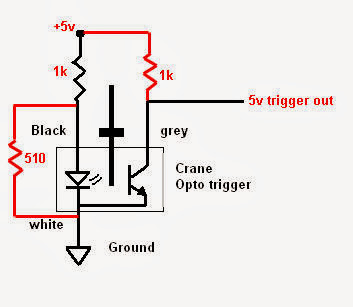
Just an update... As of today this is running with a new LED. I ended up not using the voltage divider and just put a 330 ohm resister in front of the black wire, power to the led, and used a 1k resistor to pull up 5v to the gray wire. nice clean signal ~0-5v. won't be able to drive till the salt is off the road but it idles nice in the garagejuki48 wrote:FYI, I'm pretty sure 5v borked the infrared led in the crane 700-0020 sensor. mine is dead after testing it out on the bench. I took it apart and there is nothing to limit current in there. I looked up replacement led's online and noticed there are none rated for more than 2 volts.also, the crane sensor will need a 5v pullup with 10mA current max. I think I'll make a little adapter with a voltage divider and 1k pullup resistor so I can power the led with ~1.6v and provide the 5v for the photo transistor to pull down. like this
I can easily put those 3 resistors in the harness connected to the sensor.
Riley
74 Ghia 2276 Turbo MSII Extra
67 Beetle in restoration
Manx Style buggy 1600 stock
74 Ghia 2276 Turbo MSII Extra
67 Beetle in restoration
Manx Style buggy 1600 stock
-
juki48
- Posts: 473
- Joined: Wed Apr 04, 2007 9:04 am
Re: cam and crank trigger combo inside a distributor (megasq
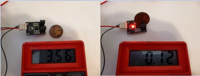
I got my little optical sensors from china today. these are really neat and SUPER cheap, ~$3 shipped. seems like a very good option for an optical trigger. they should be able to handle very high tooth counts too, higher than anyone will want to make unless you have access to a laser cutter. the led would also be helpful for initial setup and troubleshooting. in this photo I am running it off 5v and it outputs 3.56. wish I had found these before I spent $30 on a crane cams sensor.
Riley
74 Ghia 2276 Turbo MSII Extra
67 Beetle in restoration
Manx Style buggy 1600 stock
74 Ghia 2276 Turbo MSII Extra
67 Beetle in restoration
Manx Style buggy 1600 stock
-
Devastator
- Posts: 3493
- Joined: Tue Nov 06, 2007 6:51 am
Re: cam and crank trigger combo inside a distributor (megasq
Neat!
Devastator's Build Thread
Sandrail
2.4 liter, supercharged Chevy Ecotec
"If everything seems under control, you're just not
going fast enough."
Mario Andretti
Sandrail
2.4 liter, supercharged Chevy Ecotec
"If everything seems under control, you're just not
going fast enough."
Mario Andretti
-
Redline Weber
Cam and crank trigger combo inside a distributor "Optical"
OK Juki, A GOOD LESSON taught from NASCAR before my 60-2 TW was fitted to the GN engine.
The under-hood temps reached over 300F melting the magnetic flux inside the REQUIRED MSD Nascar approved distributor.
The "fix" was to go OPTICAL.
THIS method also allowed for NO dirt on the sensor.
Method : Your optical board could be located remotely, away from the engine.
Then fit a light pipe to communicate the required signal from the shutter
wheel to your sensor and light source.
Worth a try ?
Lance
-
juki48
- Posts: 473
- Joined: Wed Apr 04, 2007 9:04 am
Re: Cam and crank trigger combo inside a distributor "Optica
Are you saying they were using magnets that were degrading from temperature? if so, why not use higher temp rated magnets? if your not saying that, I don't know WTF you are talking about... I design solenoids that work at 220°C and my flux doesn't meltRedline Weber wrote:melting the magnetic flux
Riley
74 Ghia 2276 Turbo MSII Extra
67 Beetle in restoration
Manx Style buggy 1600 stock
74 Ghia 2276 Turbo MSII Extra
67 Beetle in restoration
Manx Style buggy 1600 stock
-
Piledriver
- Moderator
- Posts: 22520
- Joined: Sat Feb 16, 2002 12:01 am
Re: cam and crank trigger combo inside a distributor (megasq
I think he said they used fiber optics to get the electronics away from engine heat.
(Good plan)
Some of the engineering plastic fiber will take quite a bit of heat, and glass multimode will take ... whatever abuse glass fiber and kevlar will tolerate.
Probably not an issue for most applications.
(Good plan)
Some of the engineering plastic fiber will take quite a bit of heat, and glass multimode will take ... whatever abuse glass fiber and kevlar will tolerate.
Probably not an issue for most applications.
Addendum to Newtons first law:
zero vehicles on jackstands, square gets a fresh 090 and 1911, cabby gets a blower.
EZ3.6 Vanagon after that.(mounted, needs everything finished) then Creamsicle.
zero vehicles on jackstands, square gets a fresh 090 and 1911, cabby gets a blower.
EZ3.6 Vanagon after that.(mounted, needs everything finished) then Creamsicle.
-
Paul H
- Posts: 744
- Joined: Wed Jan 22, 2003 12:01 am
Re: cam and crank trigger combo inside a distributor (megasq
So does it all work then or do we have a barrel of broken biscuits ( English for nonsense )