Also, I have a condenser on the top of my generator..?? The wire on that is broke off.. I was assuming that was there for something they may have wired in afterwards.. (radio maybe?) Would that have anything to do with the car not firing up?
74 Beetle Fuse Box Diagram/Ignition Diagram
-
gllevand
- Posts: 1
- Joined: Sun Aug 28, 2016 1:41 pm
74 Beetle Fuse Box Diagram/Ignition Diagram
Hi! I just got a 74 Beetle and the wiring is a mess.. I am able to crank the engine over but I have no spark to fire it up. I am pretty positive I have the new ignition coil wired correctly.. Would the wiring from the ignition switch/module have any effect on getting a spark? Could that module be bad? I would like to follow a diagram and just go through the entire car and make sure things are all in fact wired correctly.. A lot of cut wires and the fuse box itself looks like a nest of wires.. I would like to clean it all up for my own sanity!  Any resources and advice would be very helpful! Thanks in advance!
Also, I have a condenser on the top of my generator..?? The wire on that is broke off.. I was assuming that was there for something they may have wired in afterwards.. (radio maybe?) Would that have anything to do with the car not firing up?
Also, I have a condenser on the top of my generator..?? The wire on that is broke off.. I was assuming that was there for something they may have wired in afterwards.. (radio maybe?) Would that have anything to do with the car not firing up?
-
Marc

- Moderator
- Posts: 23741
- Joined: Thu May 23, 2002 12:01 am
Re: 74 Beetle Fuse Box Diagram/Ignition Diagram
Extra capacitor was a filter for radio noise, would have no effect on the ignition system.
If this is a US-market`74 it's unique in that it has a seatbelt interlock relay - those were all disabled long ago, but all they did was unplug the seat sensors so solenoid control current still needs to pass through a set of contacts inside the relay. You're cranking now, but that'll change someday if you don't bypass the relay by splicing the two largest wires going to it together.
There's no "ignition module" on the car - stock they just have a basic Kettering ignition using points. A popular "upgrade" is to install an electronic pickup inside the distributor (such as a Pertronix). Points have one wire (normally green) going from the distributor to the negative terminal ("1") on the coil. Electronic pickups typically have a black one to Term 1 and a red one to the positive terminal ("15") - get those backwards and the pickup fries as a rule.
First thing to find out is if power is getting to Term 15 of the coil while cranking (it's not uncommon for the ignition switch to fail internally so that power's there in the "on" position but drops out when you go to crank).
Assuming you still have points and there's power to the coil, follow these steps to check out the system:
Disconnect the Term 1 (-) wire from the coil, leaving only the power from the ignition switch hooked up to Term 15 (+)...the electric choke, idle cutoff solenoid, and backup light fuse all receive power from Term 15 as well - they can be disconnected for now and hooked back up after you get the ignition working.
Remove the high-tension lead from the center of the distributor cap and hold the end of it <½" from anything it'll reach that's grounded (the coil bracket, base of the carb, etc.)
Turn on the ignition, and using a jumper wire between Term 1 and ground, see if you don't get a decent spark each time you disconnect it (if not you may not have power to the coil, or the coil is defective).
Next hook the Term 1 wire back up, rotate the engine until the points in the distributor are closed and see if you can get a good spark each time you open the points by diddling them with a small screwdriver; also try rotating the engine so that the points are open and then bridge across them with your screwdriver tip. If the screwdriver makes better points than the points do, they need attention. If you get a good spark under these tests but not when the engine's cranking, and the voltage to the coil isn't being dragged down excessively while cranking, then the condenser is suspect.
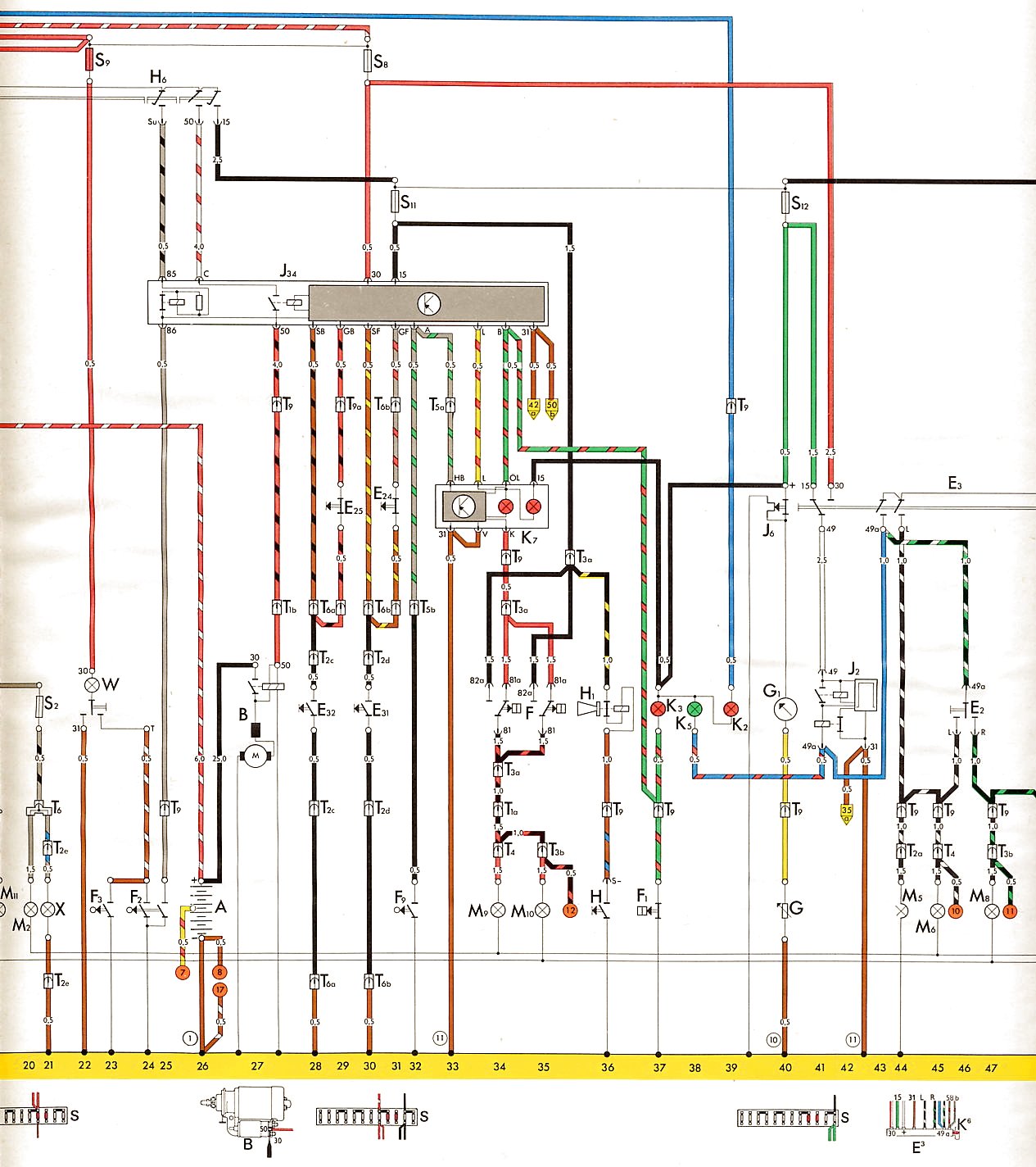
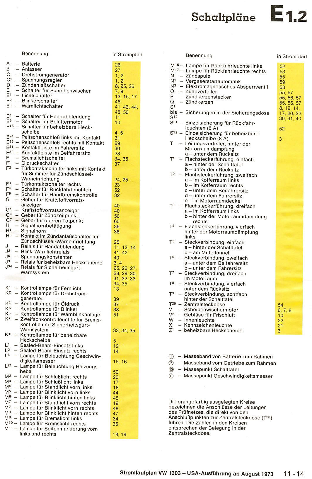
Starting in 1973, VW abandoned their old "pictorial" wiring diagrams and adopted "current track" schematics, which most people find a lot harder to follow. Many things on a `74 are the same as on a `72 so the old-style diagram can be used to help find components and the color-coding of the wires, but you should use the `74 schematic as the ultimate reference (some things, like that seatbelt interlock system, only appear on the `74 diagrams)
Newer printings of the official "Bentley" manual have gone to black & white electrical diagrams which are a real P.I.T.A. to read, but the original colored ones are available online. Here's the 1974 (US) diagram - the legend calling out the components by number is in German, unfortunately:
http://www.vintagebus.com/wiring/1303_U ... 1973-1.jpg
http://www.vintagebus.com/wiring/1303_U ... 1973-2.jpg
http://www.vintagebus.com/wiring/1303_U ... 1973-3.jpg
http://www.vintagebus.com/wiring/1303_U ... 1973-4.jpg
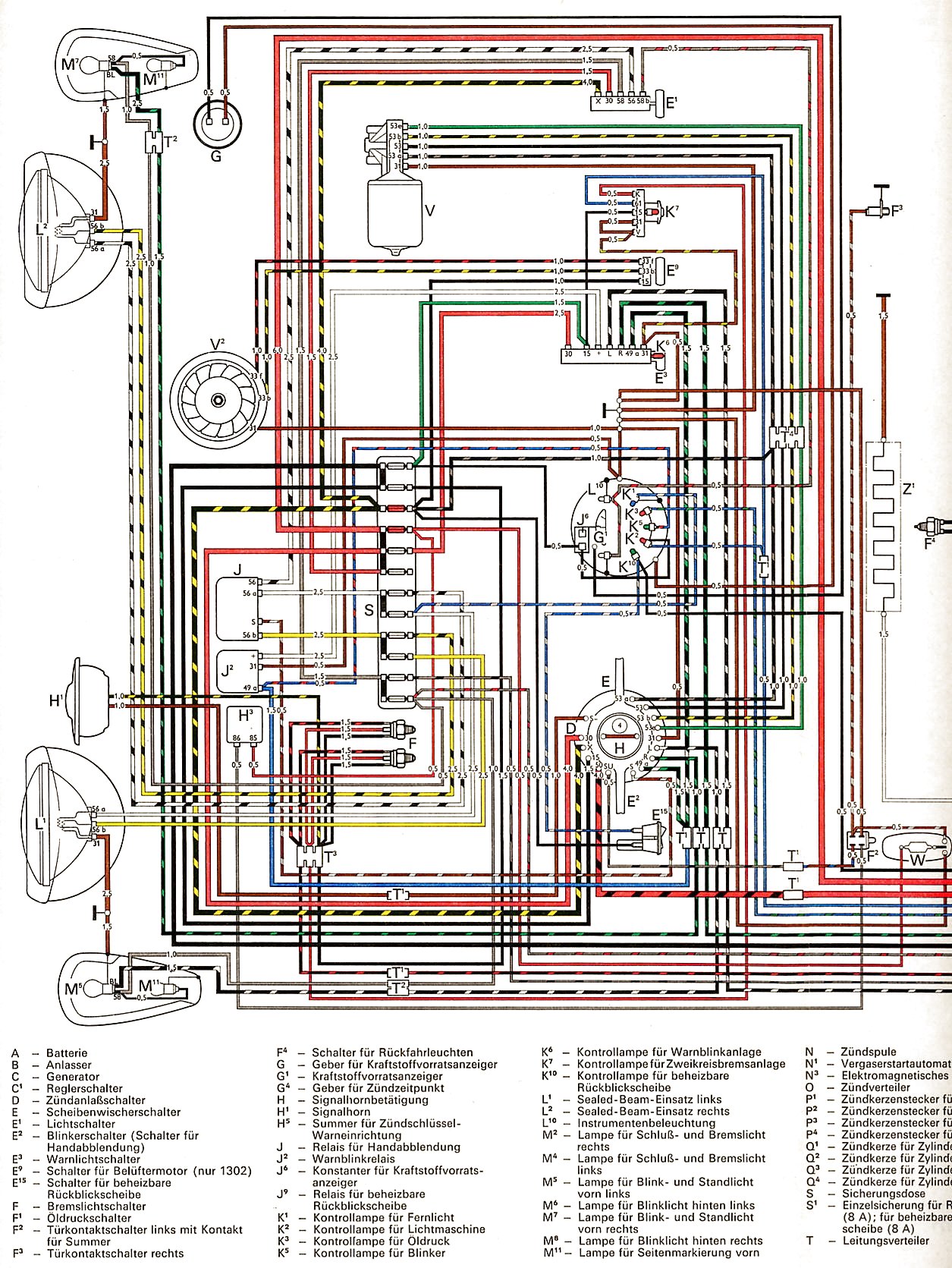
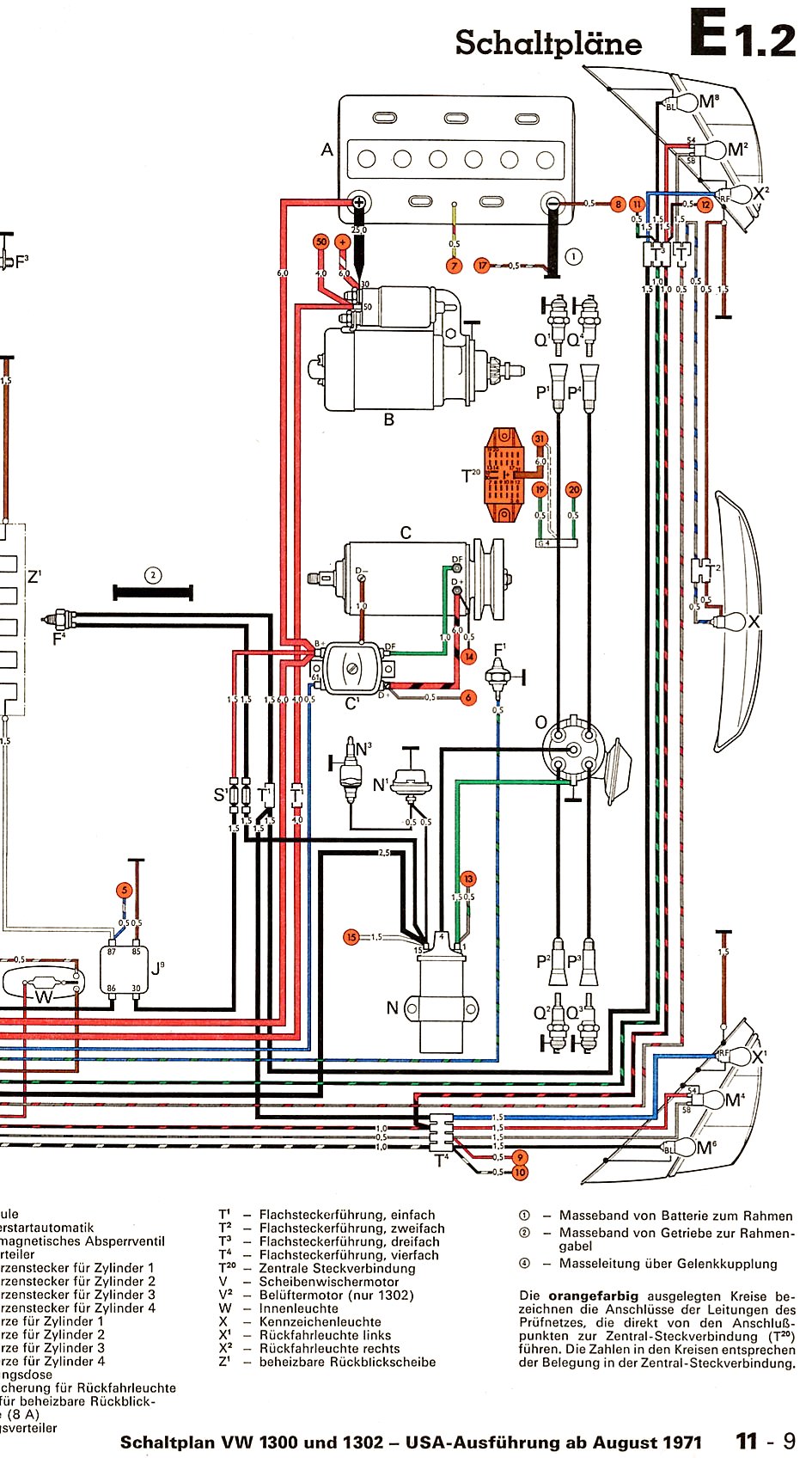
FWIW, here's the 1972 diagram:
http://www.vintagebus.com/wiring/1300_a ... 1971-1.jpg
http://www.vintagebus.com/wiring/1300_a ... 1971-2.jpg
If this is a US-market`74 it's unique in that it has a seatbelt interlock relay - those were all disabled long ago, but all they did was unplug the seat sensors so solenoid control current still needs to pass through a set of contacts inside the relay. You're cranking now, but that'll change someday if you don't bypass the relay by splicing the two largest wires going to it together.
There's no "ignition module" on the car - stock they just have a basic Kettering ignition using points. A popular "upgrade" is to install an electronic pickup inside the distributor (such as a Pertronix). Points have one wire (normally green) going from the distributor to the negative terminal ("1") on the coil. Electronic pickups typically have a black one to Term 1 and a red one to the positive terminal ("15") - get those backwards and the pickup fries as a rule.
First thing to find out is if power is getting to Term 15 of the coil while cranking (it's not uncommon for the ignition switch to fail internally so that power's there in the "on" position but drops out when you go to crank).
Assuming you still have points and there's power to the coil, follow these steps to check out the system:
Disconnect the Term 1 (-) wire from the coil, leaving only the power from the ignition switch hooked up to Term 15 (+)...the electric choke, idle cutoff solenoid, and backup light fuse all receive power from Term 15 as well - they can be disconnected for now and hooked back up after you get the ignition working.
Remove the high-tension lead from the center of the distributor cap and hold the end of it <½" from anything it'll reach that's grounded (the coil bracket, base of the carb, etc.)
Turn on the ignition, and using a jumper wire between Term 1 and ground, see if you don't get a decent spark each time you disconnect it (if not you may not have power to the coil, or the coil is defective).
Next hook the Term 1 wire back up, rotate the engine until the points in the distributor are closed and see if you can get a good spark each time you open the points by diddling them with a small screwdriver; also try rotating the engine so that the points are open and then bridge across them with your screwdriver tip. If the screwdriver makes better points than the points do, they need attention. If you get a good spark under these tests but not when the engine's cranking, and the voltage to the coil isn't being dragged down excessively while cranking, then the condenser is suspect.
Starting in 1973, VW abandoned their old "pictorial" wiring diagrams and adopted "current track" schematics, which most people find a lot harder to follow. Many things on a `74 are the same as on a `72 so the old-style diagram can be used to help find components and the color-coding of the wires, but you should use the `74 schematic as the ultimate reference (some things, like that seatbelt interlock system, only appear on the `74 diagrams)
Newer printings of the official "Bentley" manual have gone to black & white electrical diagrams which are a real P.I.T.A. to read, but the original colored ones are available online. Here's the 1974 (US) diagram - the legend calling out the components by number is in German, unfortunately:
http://www.vintagebus.com/wiring/1303_U ... 1973-1.jpg
http://www.vintagebus.com/wiring/1303_U ... 1973-2.jpg
http://www.vintagebus.com/wiring/1303_U ... 1973-3.jpg
http://www.vintagebus.com/wiring/1303_U ... 1973-4.jpg
FWIW, here's the 1972 diagram:
http://www.vintagebus.com/wiring/1300_a ... 1971-1.jpg
http://www.vintagebus.com/wiring/1300_a ... 1971-2.jpg