Home made rotisserie
Posted: Sun Nov 16, 2014 8:07 pm
I just did a search to see if I ever did document my rotisserie but it looks like I didn't at lest in the tool area. I have also have a couple of things I would change on mine which I would like to document.
First, I built this thing either in the mid to late 90's or early 2000s so it has been around a lot as well as a lot of photos taken and posted here.
I used two HF 750# engine stands, on sale, to do my build with. Since the main post is angled back to allow the cantilevered weight to straighten out the main post and since I am not going to put that much weight on it, cantilevered on one stand that I so I had to accommodate for that.
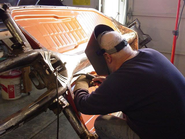
This was taken today and it shows the location of the notch I took out of the front of the rectangular tube to straighten out the main post; I marked the notch then using a cut off tool I took out the three sides of the tube. Actually I made the same cut to both stands the put the assembled stands back to back and aligned the main posts to be straight up I also had got a piece of tube that is the same outside diameter as the inside diameter of the pivot piece then leveling them out by clamping the tube to both pivots and rechecking the main posts for being vertical I tacked then welded them back together. As far as making the basic stands that was about it.
One thing I got lucky on: While I think I did, I don't remember if I measured the mid-point of the pan vs. the lower leg of the stand and if I could rotate the rotisserie all the way around which I can do... a type I anyway. I doubt it would handle a rail w/cage, as far as a type III goes I am not sure about in any way and if you are thinking about a bus... are you kidding!
Corrections I would make to the basic stand.:
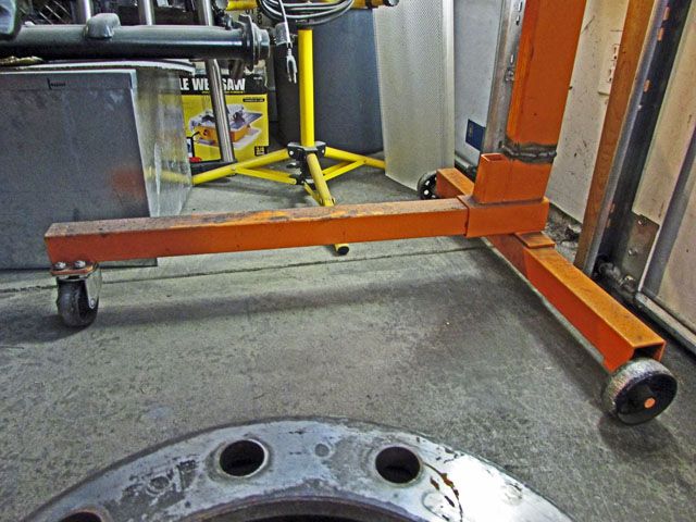
On seeing the adapted stand on the show two things that I thought about were done. The front wheel on the stand was moved probably half way back or more towards the other wheels and the front legs on both parts were trimmed back. I couldn't remember just how close they were so I went out and was going to measure the gap but it is so far away it shouldn't be a problem. One thing the single wheel moved back does is allow for tighter turns when rotating the pan to work on the left side after working on the right side if you have a tight work area (I have to go outside to swing things around). The long wheel base of each stand does make it a bit longer of a circle you have to pivot around. The commercial rotisserie had a square tube that joins the two stands; it fit inside of the front legs and needs to be bolted/locked in place.
Normally I would say to weld two nuts per stand to allow bolts to jam down on the square tub to lock it in place. Thinking about it, I think I would put the bolts on the under side as the pan does come pretty close to the legs. The other option is to raise the main post which is harder to do but makes more sense.... maybe!
There are two basic weaknesses I have found as together and unmodified, they both together can accommodate a shorter wheel base pan but really need the stiffness of the joining tube. Mine does need it also especially when moving it around to face the other direction.
Recently I was watching one of those auto rebuild shows and during a short piece I saw the guy rotating the car on the stand and noticed two things. One was that he was using a pipe in a tube to turn the car (see below) and the other was accommodations' to chassis/body length adaption.
The next part deals with the rotating part of the engine stands:
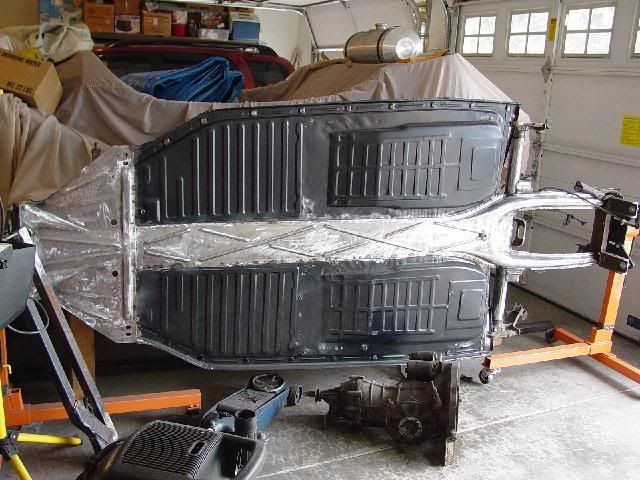
I used the stock arms of the engine stand and the bolts that attach the front beam to lock the frame head to the engine stand. In the rear I made an H-shaped mount using scrap and attached the stand to the pickle forks using the stock bolts. I used the arms on both stands to level out the pan and also to clear the legs of the now a rotisserie.
Changes to the rotating part of the now rotisserie:
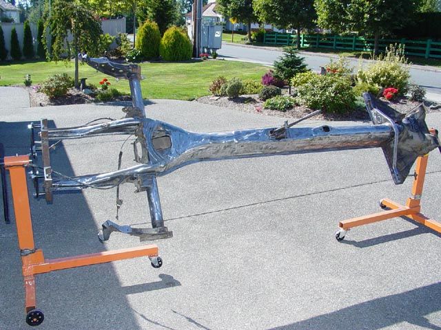
One thing I was not aware of at the time was the 4° to 6° lay back of the frame head to accommodate the front beam caster so when I move things the front wheel comes up (see the top picture) but there is enough slop in the engine stand rotating devices to accommodate this... except you need a hammer to re-align the holes for locking the position of the heads (more on that later).
I am not sure if the rear transaxle/pickle forks have some angle added or not to account for deflection when the engine and transaxle are mounted but now I think there is an fix that can be made thanks to the one quick view of a purchased rotisserie that I already have alluded to.
http://www.mooreparts.com/8428-AC430036-24%2A/
These are EMPI and there is 24 of them in the package but this is the idea; I am sure you can get them elsewhere also. You will need at least 8 of them, maybe more depending on how you attack this change.
On the front I would use a shortened front beam that will fit the year of pan you are using. After trimming off the ends (a bent axle would be nice if it weren't been too far inboard) then weld a threaded bolt to accommodate the engine mount pieces on the now rotisserie. On one or the other clams on the front you will probably need to make a spacer to accommodate the caster of the frame head.
I the rear I would use a tube longer than the spread of the transaxle mounts and tab it then bolt it to the mount. I would then use these clamps and make similar mounts (intentionally vague as there should be several ways to do this) to accommodate and angle in the transaxle mount... if any.
On my rotisserie there are four holes in the pivot of the head which are sloppy but allow you to sit the pan horizontal tunnel up or down, vertical left or right and ...
... at ~45° tipped left or right. By closing off the holes with weld/making a new tube and putting a jam bolt or two on the pivot you can do closer intervals of change. Not completely sure if that is a good idea or not assuming you are one that climbs all over everything. This will give an idea of the hight off the floor and an advantage to pan rotation.
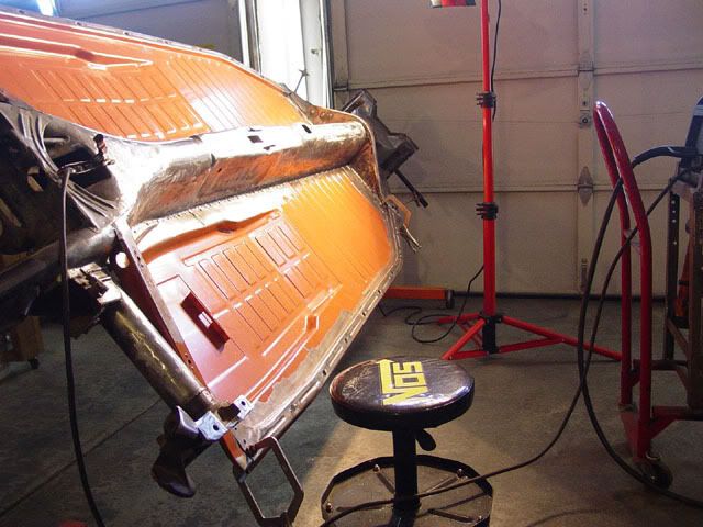
The pan is high enough to work on without having to lean too far over assuming you are ~6' or under. Tilting it also allows for some fanny support at times as shown in one picture.
Other than rotating it around horizontally in a close shop it is easy to move around and rotate. I did a lot of work on the pan with it standing vertical (on edge) too which made it easy and storing the pan on edge is a lot nicer than it setting on jack stand horizontal to the floor. It is hard to mount the beam when on the rotisserie which is too wide to be rotated if and when mounted on the rotisserie. The rear trailing arms can be done on the rotisserie but not rotated to anything much more than 45 degrees as the trailing arms will hit the front leg of the stand.
One additional thing about using the tubes is the handles on the motor stand are short of leverage as they are short and mounted inboard. I usually gab or also grab the pan itself to help rotate. The same handles could be used as levers in the ends of the tubes making things a lot easier to rotate.
I am welcome to any other ideas, corrections or what ever.
Lee

First, I built this thing either in the mid to late 90's or early 2000s so it has been around a lot as well as a lot of photos taken and posted here.
I used two HF 750# engine stands, on sale, to do my build with. Since the main post is angled back to allow the cantilevered weight to straighten out the main post and since I am not going to put that much weight on it, cantilevered on one stand that I so I had to accommodate for that.

This was taken today and it shows the location of the notch I took out of the front of the rectangular tube to straighten out the main post; I marked the notch then using a cut off tool I took out the three sides of the tube. Actually I made the same cut to both stands the put the assembled stands back to back and aligned the main posts to be straight up I also had got a piece of tube that is the same outside diameter as the inside diameter of the pivot piece then leveling them out by clamping the tube to both pivots and rechecking the main posts for being vertical I tacked then welded them back together. As far as making the basic stands that was about it.
One thing I got lucky on: While I think I did, I don't remember if I measured the mid-point of the pan vs. the lower leg of the stand and if I could rotate the rotisserie all the way around which I can do... a type I anyway. I doubt it would handle a rail w/cage, as far as a type III goes I am not sure about in any way and if you are thinking about a bus... are you kidding!
Corrections I would make to the basic stand.:
On seeing the adapted stand on the show two things that I thought about were done. The front wheel on the stand was moved probably half way back or more towards the other wheels and the front legs on both parts were trimmed back. I couldn't remember just how close they were so I went out and was going to measure the gap but it is so far away it shouldn't be a problem. One thing the single wheel moved back does is allow for tighter turns when rotating the pan to work on the left side after working on the right side if you have a tight work area (I have to go outside to swing things around). The long wheel base of each stand does make it a bit longer of a circle you have to pivot around. The commercial rotisserie had a square tube that joins the two stands; it fit inside of the front legs and needs to be bolted/locked in place.

Normally I would say to weld two nuts per stand to allow bolts to jam down on the square tub to lock it in place. Thinking about it, I think I would put the bolts on the under side as the pan does come pretty close to the legs. The other option is to raise the main post which is harder to do but makes more sense.... maybe!
There are two basic weaknesses I have found as together and unmodified, they both together can accommodate a shorter wheel base pan but really need the stiffness of the joining tube. Mine does need it also especially when moving it around to face the other direction.
Recently I was watching one of those auto rebuild shows and during a short piece I saw the guy rotating the car on the stand and noticed two things. One was that he was using a pipe in a tube to turn the car (see below) and the other was accommodations' to chassis/body length adaption.
The next part deals with the rotating part of the engine stands:
I used the stock arms of the engine stand and the bolts that attach the front beam to lock the frame head to the engine stand. In the rear I made an H-shaped mount using scrap and attached the stand to the pickle forks using the stock bolts. I used the arms on both stands to level out the pan and also to clear the legs of the now a rotisserie.
Changes to the rotating part of the now rotisserie:
One thing I was not aware of at the time was the 4° to 6° lay back of the frame head to accommodate the front beam caster so when I move things the front wheel comes up (see the top picture) but there is enough slop in the engine stand rotating devices to accommodate this... except you need a hammer to re-align the holes for locking the position of the heads (more on that later).
I am not sure if the rear transaxle/pickle forks have some angle added or not to account for deflection when the engine and transaxle are mounted but now I think there is an fix that can be made thanks to the one quick view of a purchased rotisserie that I already have alluded to.
http://www.mooreparts.com/8428-AC430036-24%2A/
These are EMPI and there is 24 of them in the package but this is the idea; I am sure you can get them elsewhere also. You will need at least 8 of them, maybe more depending on how you attack this change.
On the front I would use a shortened front beam that will fit the year of pan you are using. After trimming off the ends (a bent axle would be nice if it weren't been too far inboard) then weld a threaded bolt to accommodate the engine mount pieces on the now rotisserie. On one or the other clams on the front you will probably need to make a spacer to accommodate the caster of the frame head.
I the rear I would use a tube longer than the spread of the transaxle mounts and tab it then bolt it to the mount. I would then use these clamps and make similar mounts (intentionally vague as there should be several ways to do this) to accommodate and angle in the transaxle mount... if any.
On my rotisserie there are four holes in the pivot of the head which are sloppy but allow you to sit the pan horizontal tunnel up or down, vertical left or right and ...


... at ~45° tipped left or right. By closing off the holes with weld/making a new tube and putting a jam bolt or two on the pivot you can do closer intervals of change. Not completely sure if that is a good idea or not assuming you are one that climbs all over everything. This will give an idea of the hight off the floor and an advantage to pan rotation.
The pan is high enough to work on without having to lean too far over assuming you are ~6' or under. Tilting it also allows for some fanny support at times as shown in one picture.
Other than rotating it around horizontally in a close shop it is easy to move around and rotate. I did a lot of work on the pan with it standing vertical (on edge) too which made it easy and storing the pan on edge is a lot nicer than it setting on jack stand horizontal to the floor. It is hard to mount the beam when on the rotisserie which is too wide to be rotated if and when mounted on the rotisserie. The rear trailing arms can be done on the rotisserie but not rotated to anything much more than 45 degrees as the trailing arms will hit the front leg of the stand.
One additional thing about using the tubes is the handles on the motor stand are short of leverage as they are short and mounted inboard. I usually gab or also grab the pan itself to help rotate. The same handles could be used as levers in the ends of the tubes making things a lot easier to rotate.
I am welcome to any other ideas, corrections or what ever.
Lee