metal band saw

General tips/tricks/tools that could be utilized on any platform.
Ol'fogasaurus
Posts: 17756
Joined: Mon Nov 13, 2006 10:17 pm

metal band saw

Post by Ol'fogasaurus »

I think I am in the position of looking for a vertical band saw.

Image

Image

Currently I have this, an old ENCO that I bought new over 20 years ago. If you get it set up correctly, get a good bi-metal blade with the proper tooth count and crank the band adjuster down very tight (the key to the whole thing) you can cut, horizontally, a piece of metal off with a very close to 90° cut. Looking on line at places like Craig’s list I see them (the same tool with different paint and/or decals from different companies) for sale for as low as $75 and some seemingly gold plated ones for prices above what you can buy them for new… even the JET version of the same thing.

The big drawback to them is when you are cutting vertically. The platen supplied is next to worthless and you have to change the platen from the horizontal one to the larger vertical one which is so awkward to do you wear out the cross/phillips head on the two screws. You then are at an awkward position to cut in, and the unit can get tippy in the direction you are feeding the material to be cut in so you end up sitting on the machine itself. The stand for the machine is flimsy at best and is always vibrating the screws out.

You can http://www.homemetalshopclub.org/projec ... stand.html and http://www.mini-lathe.com/Bandsaw/Bandsaw.htm (a lot of good information on the second URL) but you are still limited in vertical cutting direction.

Looking around I found a two speed 14” wood/metal band saw at Tool Town for $250. When talking to someone several years ago I was told to get a gear driven unit which are really expensive but since I am a home/garage metal screwer-upper do I need more than this.

I also found a JET 14" Vertical Metal / Wood Band saw ~ Model J-8201K - $895 (http://www.jettools.com/us/en/p/j-8201k ... 1ph/414500) at a scratch and dent sale locally. This is a 120 volt unit and it normally sells for anywhere around $1400 to $1600.

I did look into Grizzly which is around 80 to 100 miles north of here but they don’t have anything in the under $1000 price range and in 120 volt.

So, does anyone have any good ideas/advice? I don’t want to pay shipping if I don’t have to.

Lee
User avatar
Dale M.
Posts: 1673
Joined: Mon Oct 05, 2009 8:09 am

Re: metal band saw

Post by Dale M. »

Just build a good table and vertical cutting in not a problem.... We had a huge WELLS saw at work that has supplemental table and it was great as a vertical saw..... All you need as a lock system to keep saw frame in true vertical and a solid built table.... No other mods to guides or frame or blade....

Dale
"Fear The Government That Wants To Take Your Guns" - Thomas Jefferson
1970 "Kellison Sand Piper Roadster"
Ol'fogasaurus
Posts: 17756
Joined: Mon Nov 13, 2006 10:17 pm

Re: metal band saw

Post by Ol'fogasaurus »

Thanks Dale, as usual good advice.

A larger platen is part of one of the band saw remodels shown as URLs and it is an option that I am still considering plus that mod would save money but my history with the saw and trying to cut with it as a vertical saw is still in the way :lol: . One of the objections to doing that is that it now is getting away from the small storable unit to: why not be done with it and get a dedicated vertical unit. With the larger platen you still have to change back to the smaller platen if you want to cut horizontal... OMG, it just came to me: with the cheaper cost of some I have seen on Craig's List I could get a second one and make one dedicated vertical and one horizontal.... NOT! :roll: :lol:

Its has tried to tip over on me in any of the three possible directions (to each side and tip over backwards plus as I roll it out from storage) once too many times even with me sitting on it (and I am a 'pudgy bunny') it can be tippy so I am still looking at options but... at the same time... a different but wider base w/a throne is an option.

By-the-way, in one of the biker build shows in the mid-2000s, during one of the competitions between a couple of builders one of the guys got so frustrated with this type of saw he went coo-coo in the coco and smashed his up with a sledge hammer while being filmed (they were under a time limit and the blade popping off all the time which they can do if the blade tension is not run down extra tight. I've been cut a couple of times when just at the wrong moment [the right moment for the blade :wink: ]) finally got to him in a negative way. I think he felt good after his TT and he did end up with a pretty nice band saw afterwards (I think it was the TV show that may have purchased it in order to complete the episode. Oh well... "That's entertainment" [sing the jingle as you read this last sentence])!

(for those of you that already have one of these) Speaking of the blade popping off issue, that seems to be common with these cheaper band saws; during one period of time when it was popping off every few minutes I got frustrated and cranked down on the adjuster, as hard as I could and way harder than I thought it should be (a TT... probably) and the blade stayed in place. Since then I have gone through several blades now (usually spitting teeth [cheap box store blades I think] but a couple have just worn out) and I have had one come undone at the seam but that was before I started tightening the blade up so much. I highly recommend getting bi-metal blades as they wear much better and don't have a tendency to spit teeth off especially in long sections. Like I said, I have had this little jewel a long time and have done a fair amount of work with it. It gets used in spasms' so-to-speak.

Lee
User avatar
Dale M.
Posts: 1673
Joined: Mon Oct 05, 2009 8:09 am

Re: metal band saw

Post by Dale M. »

Adding a little bit better set of wheels, wider stand and moving them back further would change CG greatly and make it more stable....

Luckily you are not dealing with old Craftsman Professionals like I am, got it at yard sale for 20 bucks and its old and tired and sometime decides to change blade direction in middle of cut.... Blade is cutting on left hand side and not on right hand side like most saws... PO (real redneck) didn't understand you had to flip blade inside out to get teeth going right direction... Motor was fill of dirt (mud dobber nests) and all the bearings were dry and electrical cord where scary... Mine wont even go vertical best it can do is about 45 degrees....

Dale
"Fear The Government That Wants To Take Your Guns" - Thomas Jefferson
1970 "Kellison Sand Piper Roadster"
Ol'fogasaurus
Posts: 17756
Joined: Mon Nov 13, 2006 10:17 pm

Re: metal band saw

Post by Ol'fogasaurus »

In the two URLs I added they talk about different stand designs with cutting fluid also. Even with this stand (http://www.homemetalshopclub.org/projec ... stand.html_) when you are in the vertical position you are pretty far away from the platen and blade which may be good or may be bad. If you didn't put the cutting liquid drip in then you might be able to shift the saw around a bit giving you a better reach to the platen but you are still having to reach.

Your old Craftsman sounds kind of like a couple I have seen. Tired and abused. I accidentally put the blade on backwards once; caught it before I started it up. When I had unwound the blade from the package it jumped on me and went inside out and I didn't catch it until something looked a bit weird :oops: :lol: .

Here is another site for metal working information: http://www.homemetalshopclub.org/news/article_sort.htm

Lee
Ol'fogasaurus
Posts: 17756
Joined: Mon Nov 13, 2006 10:17 pm

Re: metal band saw

Post by Ol'fogasaurus »

I found out that the blade speed for metal is too fast. thanks anyway.

Lee
Ol'fogasaurus
Posts: 17756
Joined: Mon Nov 13, 2006 10:17 pm

Re: metal band saw

Post by Ol'fogasaurus »

Well I almost am through dooding it.

My stand for the band saw was getting to old and bent up from moving it around for roughly 30 years and it was getting dangerous so I want out and got the material that the plans I posted said and started cutting metal.

Image

This is the old stand and how it is used vertically. It turns out not much had changed that way.

Image

This is the stand part way through the build. It sits lower but does move around better. The plans are incomplete and, in my opinion they are wrong in a couple of places. I have lost some pictures already so I am going to have to see if I can find where they went as some clues on bending flat stock is in there... assuming anyone wants to see them.

Image

The first thing you do is make the pan which I though would be the hardest but it wasn't... the frame was. Again, doing some figuring while you are building will get you over a couple of the humps. Maybe it's me but I got lost with the similar sized, shape and odd cuts on some pieces so some advice: Letter each piece per the plans and put an arrow pointing up; it will make life a lot easier. Also you are going to have to radius a lot of things which he doesn't tell you (remember, this guy is a machinist I think by the way things are done).

The verticals I pre-built before installing them to make sure they were square and sat at the same height after tacking them in place... you'll figure that out when you get there. The spacing is not given for the two vertical assemblies or rather the spacing for the rear vertical assembly is not give but it is centered on the mounting bolts on the saw itself. The pan is just about perfect a you can get dimension wise.

Image

Image

This is where I am now. I have to figure out a handle system as I don't particularly care for his design. Once that is done the saw can come back off, finish welding and paint but I'm not sure of the color yet.

Lee
Ol'fogasaurus
Posts: 17756
Joined: Mon Nov 13, 2006 10:17 pm

Re: metal band saw

Post by Ol'fogasaurus »

I found the missing photos so I am going to post them incase they might help someone with bending thicker sheet metal.

Image

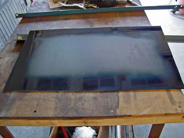
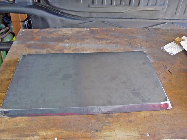
This is what the pan started as after trimming a quarter sheet of 14ga down to size. I sprayed bluing around the sides to mark out the centerline of the bend, the corner notches and the corner relief that must be added. The plans do not talk about this but it is common for flat pattern work to have them.

This shows the centerline of bend. I did not show the mold lines (this is the start and end of the bends/the point of transition where the bend starts from the flat sheet as they were not necessary to be used on this bend because of the relief cut.

Also note that I added a center punch at the intersection of the two centerlines of bend. This is to stop a condition in the bend where a stress riser is created when the two corners meet and want to jam together during bending. If the relief is not there the compressed material on the inside of the bend will not compress anymore and starts to push the outside material up causing a lift and this is where a stress fracture will start. As I remember the hole should be 2Xs the material thickness. Since 14ga is 0.0781. I kind of cheated and drilled a 1/8"(edit) hole which worked satisfactory and was easy to weld shut.

Image

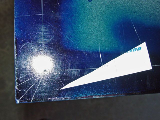
This shows the notch for bending. Since I don't have tool that I can lay flat and get the angle I made a template and used it. Unless is used the wrong dimension on the plans (totally possible) I thought the angle was too steep and was wrong which it was.

Since it has been too long since I have drawn any parts I goofed and made the angle to the intersection rather than the radius of the relief hole. I kept a cutting thin disc handy and did some relief work as I made the bends (getting old is a bitch).

Image

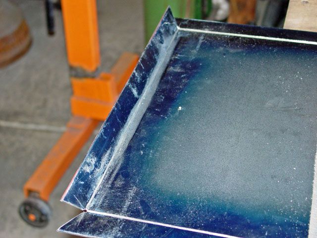
(I've already started bending here but you can see the idea of the relief cut)

This is the interesting part of the job. He does talk about the two different ways to make the bend: one is done by cutting then the welding of the separate sides; this version being the harder one do in my opinion. The bend radius of 14ga hot (?) rolled steel is going to be quite large so the inside material was relieved allowing it to be bend at a tighter radius than normal.

As I have said before: old Hollywood bed frame material is a god send for a lot of things; it can be cheap to get at "garbage" sales. I cut some material I had laying around to the length of the flange (it takes two, one for the 2 long flanges and 2 for the shorter flanges.

I laid one leg of the angle iron (always use the same leg for relieving as you will need the other leg later on) just back, about the width of a sharp pencil line along the centerline of the bend but to the inside of the line. I then used a cut off tool with a thin blade to score the centerline of bend being careful not to do anymore damage to the angle iron's face than I could. Then using the other leg of the angle iron I laid it along the cutting line and clamped it in place and used it as a bending form.

Image

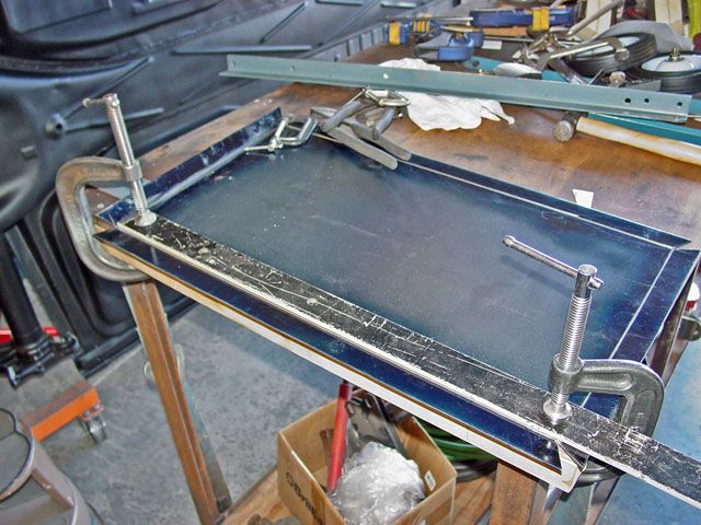
Before I ended up using the angle iron I tried using a thick piece of bar stock but the thickness of the stock ended up getting in the way so the piece of bed frame in the back ground was used. For the same reason: the strong back of the angle was not used as it too got in the way.

Image

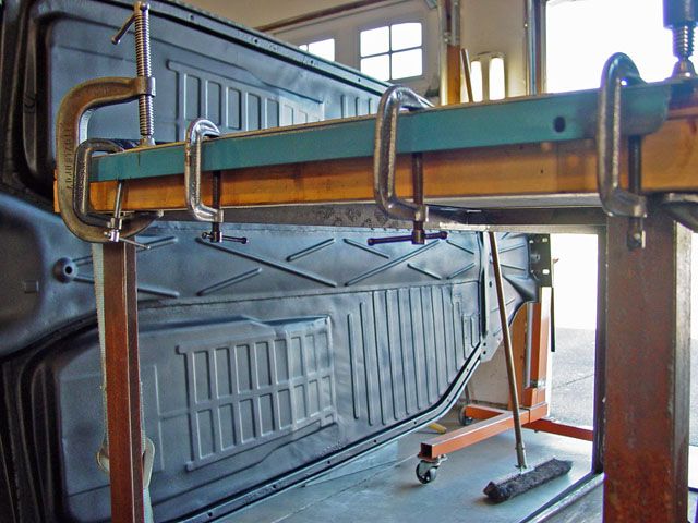
I tried several ways of bending the material with the angle on top and using two channel locks as handles to bend the flanges but it didn't work well and wanted to put lumps in the flanges which I had to body hammer and dolly out. Also the channel lock pliers wanted to open up as I lifted. Turning the pliers so that they faced the other way did not work at all so I ended up using this under the flange method and for handles I use two same sized crescent wrenches with them open to the thickness of the material of the bed frame. The combination of the flange where is was and the crescent wrenches worked so much better than I though it would.

After a couple of bends I found that it took three movements, make a bend then remove everything and measure the angle, then reinstall and bend again, etc. I was to get the angle I wanted w/o too much work or over bending.

The comic thing about this was the table I was working on I had made several years ago and I had forgotten that the top is only laying on the frame so when I lifted on the handles the top lifted too. So, brought in a tie down strap and cinched the top to the bottom legs of the table... worked good but then the whole end of the table lifted. Silly me!

I then put a foot on the lower cross-piece of the table and pivoted off that and things, including the bend, went much easier. Again, I bent first with the "handles" towards the end of the flange then moved them towards the center and pulled again. The flanges came out straight and even.

Image

Image

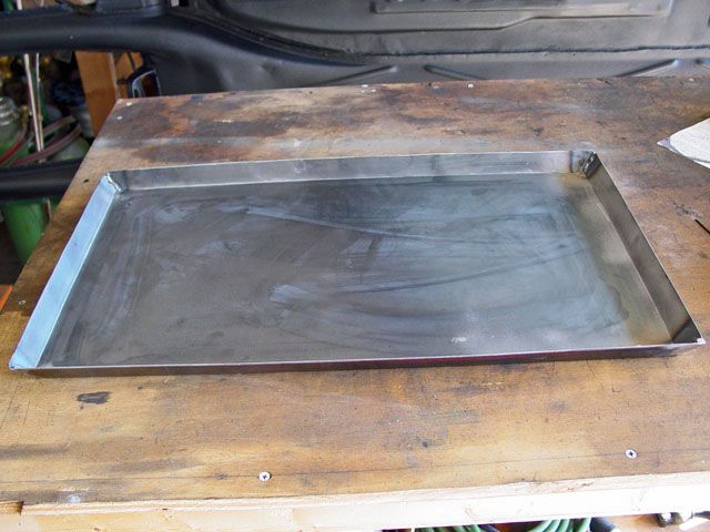
By-the-way, the relief cuts almost closed competently shut by them selves; it you want to... or need to you can weld the cutout closed with no problems. The depth of the cut was not half way through but fairly close. This you will find will be a trial and error thing so cut lite and you can always go back over it if you need to.

I hope this helps someone.

Lee
Ol'fogasaurus
Posts: 17756
Joined: Mon Nov 13, 2006 10:17 pm

Re: metal band saw

Post by Ol'fogasaurus »

I wasn't going to post again until I got it finished but I had some fun today so I thought... why not.

Some update: The stand as it sits with the band saw in place is very head heavy because the wheels are so far to the rear. When you lift it to move you are lifting quite a bit of weight but the good thing about it is that it is now very stable as compared to how it was on the original stand. If you put the saw's head up as you would to use it as a vertical saw the saw does not seem light and want to flop to the rear like it did. You used to have to lift it carefully which sometimes did not happen so you had to move quickly. It is also not seemingly as top heavy as it was side to side.

The carriage bolts I used are 3/8" X 2" long but I think I may upgrade to 1/2" X 2 1/2" or 3" long now. I had one solid landing on the front and it was OK but with me sitting on it that is a lot of pork on the hoof to support.

I am now at towards the finishing of the stand so I have to design the lift handle. During the build I changed a few things from the original design. From the instructions parts "E" and "F" locations have been swapped. "A-B" are the same location as are "C-D" but the cross-pieces were swapped. The cart designer used the boxed into a tube "E" as the piece to have the handle on but I chose not to do it myself. I moved the stronger "E" to the rear where most of the weight is. Good idea... probably but I had though seriously to make "F" also boxed but didn't.

I did not make/use an axle as I found some stub axles for the wheels that were easier to do; I just put doublers where the axle holes are and added a piece like "G" in the back to keep the two side rails from twisting under load... which it does very nicely thank you.

Image

The handle that needs to be built s/b ~9 1/2 inches from "F" (now "E") to get it past the head of the band saw. I also would like it to fold down and out of the way so I have given it a lot of though.

Image

Using a piece of scrap 1 X 2 rectangular tube I was going to make two brackets but then what the heck, that makes it too complicated (there is going to be more on the so I am only concerned about the fun stuff this post). I decided that I could make one piece out of the rectangular tube the split it and have both sides of the first part of the handle. Shazam! (I told you I was having fun)

I marked out the design and holes on the piece of stock and allowed for some mounting tabs which I may or may not need. I also piloted the pivot holes so the locations should be the same for both sides.

Image

Since I consider the saw to be temporarily out of service which it really isn't, I just didn't want to get it more dirty than it is) I decided to cut using a 3" disc. The is the same piece of stock I used to cut some other straight lines so that straight surface is getting a bit ragged.

Image

The finished cut before clean up.

Image

I next separated both sides with the idea of making mirrored parts.

Image

The semi finished parts. I still have some work to do to them for allowing for a pivot for the mating part and maybe some strengthening of the end but the idea is here.

Lee
User avatar
itawolf
Posts: 295
Joined: Thu Sep 02, 2010 6:07 pm

Re: metal band saw

Post by itawolf »

We have an old baileigh? And marvel bandsaw that we use around the shop
Love ur setup even if you think they are old
Better than a hand saw

Now to save up some $$
For a plasma cutter!!!
RET Marine 0317 --with VW on the lobe!!
Lots of iron in the fire
Ol'fogasaurus
Posts: 17756
Joined: Mon Nov 13, 2006 10:17 pm

Re: metal band saw

Post by Ol'fogasaurus »

Yeah... a plasma cutter then I wouldn't need a band saw either. Like I said, today it was fun for some reason. On the other hand, if I got a plasma cutter then I would have to get a TIG and a plasma or water jet table and a high functioning CAD program and .... I've only got two bays of a three car garage and the wife is jealous of the room I take up with tools not to mention the mess I make now.

Lee
Ol'fogasaurus
Posts: 17756
Joined: Mon Nov 13, 2006 10:17 pm

Re: metal band saw

Post by Ol'fogasaurus »

There are enough lookers at this so I thought I would add some more information.

Image

I didn't take any in-progress pictures... sorry. During the mounting of the end brackets that everything will pivot from I did discover that I did not need the "wings" I had added so off they came.

After some fitting I marked and drilled the two pieces of angle iron I decided to use for the handle. I marked one then clamped the two pieces together back to back to make sure that the pivots holes would be located the same; I then drilled them out. I intended that the one leg of each angle iron would ride against the stiffening flange of the mounting bracket and use it as a stop so positioning of the holes had to be fairly precise. The same with the holes on the mounting brackets. I think one of the holes on the mounting bracket is a bit off and the idea of drilling through the rectangular tube didn't work as planned as I think I got a bit of travel in the drill bit. No matter I got a fix for it... later on.

After the two arms were drilled I laid them in the final position and put the drill bit through the holes and found where the contact started and the 90 position was then cut a radius to match those points. It took a couple of tries to get all the contact points cleaned up but I think took less than a half an hour for everything.

I clamped the two brackets in place using a couple of angle iron pieces to keep things flush then check the pivot holes for alignment and level and burned the brackets in place.

Image

This shows everything as it sits now. everything is square enough for government work so I am almost happy with one exception ...

Image

When rotated to a full lift position the outboard end of the left side (in the picture) handle will be ~1/4" higher than the other side which will make for an awkward lift when moving the cart around.

Image

This is how the mounting bracket looks (sorry about the crummy welds :oops: never got that good and when your in an awkward position and need to weld rather than tack this is what you sometimes get :roll: :wink: I think it is somewhat fixable when I take the saw back off to do some more of the finish welding).

Image

By adding/welding in a "Pillow Block" that the handle will land on it you can grind down the block to where both handles meet at the same angle.

The mount and handles are using a 5/16 -18 X 1 bolts with a washer between the two pieces. I also have a washer under the head and there will be one under the nut. I also have a second Nyloc (reg.) type of washer to use as a jam nut to keep the main washer from backing off and getting sloppy. The middle washer does ride the radius so it will have to be trimmed. I could make a radius'd washer (one side has a radius on the outside edge and it is usually thicker) so it does not interfere with the radius but allows most of the load to be spread out. The edge margin on the lower side of the handle is shorter than I would like and I am thinking about adding a localized doubler to it. Not sure yet as I haven't done any real lifting of the cart yet by the handles.

Also, I have used the saw to make the handles and in my opinion it works much better than it did with the old stand. Maybe it doesn't but it sure feels more solid and the sounds it makes are much easier to translate into good or bad sounds.

I think I am going to go with larger diameter, and longer carriage bolts if I can get a nut to not ride the radius of the mounting area. It feels OK but dang, some of the awkward stuff you have to cut at times makes me a bit nervous.

Speaking of that: I did have something weird happen, don't know what it was but as I was moving the assembly something felt funny like it got soft or bent but so far I have not been able to duplicate it again and could not find any damage showing. I might add a couple of gussets to the back of the rear mount that face the wheels just in case there is a weak spot there. That is a long unsupported distance for sure.

Would I do this again, a qualified ehhhh-yaaaa, I don't know. A year ago I got a metal box that turned out to be about the right size and shape that it would have worked very nicely but I went with this as it was a known factor... maybe :wink: . I could have added a door and maybe a shelf for spare saw blades and the platen for the vertical position but then if you wanted to box in this that would work also.

Lee
helowrench
Posts: 1925
Joined: Wed Aug 11, 2004 6:20 am

Re: metal band saw

Post by helowrench »

Lee,
That is some damn nice tinbending there.
and that is coming from someone who did it for a living for wuite a while.
Ol'fogasaurus
Posts: 17756
Joined: Mon Nov 13, 2006 10:17 pm

Re: metal band saw

Post by Ol'fogasaurus »

There are some great builder here but the compliment is really appreciated.

I never did any tin bending... I told them what I wanted (on drawings) and the great mechanics where I worked did the rest. I'm being totally honest in saying that I am in awe of their work and wish I could do half the things those who made the parts were able to do. It was totally amazing to see a part that you had designed; all I ever saw was lines on Mylar sheet and when you saw the solid part I remember saying once: "Oh, that's what it looks like". Its only been since I retired that I got to do a lot of this.

CAD does allow you to see things in solids that even though you knew what they looked like... they did look different in person. It is funny that there were some great engineers that could not view things spatially so you either had to sketch it out or using colored pencils color in the outside so they could visualize it. They could rotate it in their mind like you can on a computer either so it had to be hard on some of them at times.

Oh, after I posted the last part I went out and put my straight edge on the one side of the cart again that had given me problems and it was straight... until I moved the rectangular bar away from the strong back (vertical leg) of the angle and found a small bend on the outer edge of the horizontal leg that I will have to take out and make a couple of gussets out of the rectangular tube to support that area. It is in the same place as I originally had problems with when the one leg of the rear mount for the saw all of a sudden was cockeyed. I think it is a flaw in the metal not the design or over cooking it during welding. I've seen this happen before.

Thanks again. Lee
Ol'fogasaurus
Posts: 17756
Joined: Mon Nov 13, 2006 10:17 pm

Re: metal band saw

Post by Ol'fogasaurus »

Quick update on the bend: I found part of what caused the weak spot and it was done during the removal of the rear frame assembly (pieces C, D, F [remember I traded places of E and F]) and while it was still bent I apparently nicked the surface with the cut off disc so it is my fault there and some how missed seeing it. Why the piece of angle iron bent in the first place I still have no clue. When the leg C was cut loose from angle H, it slowly, after a couple of hours, returned to straight. I have no idea why as there wasn't that much welding done there at the first time the upright was welded in place and no weight involved; the two H pieces were clamped in 2 places per piece onto a flat table during this part of the assembly. The problem area and the other three upright areas will be gusseted towards the rear on the inside where there is not a vertical leg to weld to... just in case.

I also found that the straight edge I was using was straight on three of the four surfaces (using a verified 3' long straight edge) and there was a high spot in one area :shock: . There is a bend in the H but not enough to worry about as long as I gusset G and D uprights which I was going to do anyway. When you lift up on the chassis to move the cart you shift the weight to the rear which is one of the reason's I traded E and F in the first place. It may have been a good idea to box C and D like E was but that might be too late now.

I think the handle can be finished with the saw off the stand so later today I will get my engine hoist out put together to lift the saw off the stand. With the slight draft angle in the saw's casting and the bolts holding the saw on the mounting pieces there is would be too much weight on the fasteners to not have it supported now when lifting it off or putting it back in place. I have to get a couple of SAE taps to complete this and the saw needs to be out of the way anyway.

Lee
Post Reply