Hiya,
Quick question. Rebuilding a new to me 1600TP. The bearings that came out are marked .5/.75 I have checked the crank and it is definitely 0.75 under and the outside of the bearing is 0.5 over.
Don't know the history on the case so wanted to check the actual case.
Ran a engineering straight edge along #1,2,3 and got about 5 thou gap on 2.
When I torque up the case with no shells in and no stud oil seals and run a bore mic down it I am showing the mains at 1# 2.5665, #2 2.5630, #3 2.5650
This doesn't stack with the bearings being 0.5 i.e. 20 though over, as I would have expected the case to be in the 2.580 range.
Am I missing something, is it something to do with crush?
Cheers,
MM
Measuring case wear / line bore
-
Marc

- Moderator
- Posts: 23741
- Joined: Thu May 23, 2002 12:01 am
Re: Measuring case wear / line bore
Standard bore is nominally 65mm for #1/2/3 and 50mm for #4; a new case should measure no more than 2.5598".
.5mm oversize (AKA .020"-over) would be 65.5mm, or 2.5787 (no more than 2.5795") as you surmise ....I'd believe your actual measurements over the markings on the bearings - there isn't that much crush.
What is the "gap" to which you refer? The wear step that develops in the saddle where the oil groove in the bearing goes, or between neighboring saddles? The former just means it needs a line-bore; the latter would indicate that the bores are different size (proven otherwise by your bore mic readings) or the case is badly pounded out and/or warped. If it's "only" pounded out, a line-bore should make it serviceable.
While you've got it bolted together, shine a strong light in from one end while you observe from the other. If there is any light getting through at the parting line next to the center main saddle, the case is beyond economical repair.
Another test you can make is to fit new cam bearing shells and torque the case together with only a polished/lubed camshaft in place (all six of the big nuts and at least all of the small ones below the crank - the top ones aren't particularly important at this time). If you can reach into the oil pump hole with a big screwdriver and twirl the cam easily, the case isn't in too bad of shape to consider using. If it drags there are things you can do, such as hand-scraping the cam bearing faces to gain oil clearance, but it'd be far from a first-class build.
What are the engine case ID codeletters/numbers?
-
mm289
- Posts: 18
- Joined: Sun Jan 16, 2011 12:57 pm
Re: Measuring case wear / line bore
Hi Marc,
Thanks for the info - you know how it goes sometimes when you just need to write stuff down and talk about it to make sense of it all?
So after reading your reply I thought something isn't right so went back to basics and got my calibration gear out and recalibrated my bore dial gauge. Turns out someone had dropped a couple of imperial spigots in with my metric ones so there was I thinking I was using the 65mm setting and er, I wasn't - schoolboy dumb ass error.
Anyways, have now re-measured and come up with some more sensible numbers. Build sheet is below
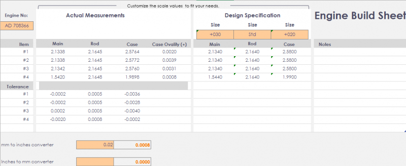
Looks like the case has been machined a few thou tight, (measurements were taken in the horizontal plane) ovality compares these to same measurements in vertical plane.
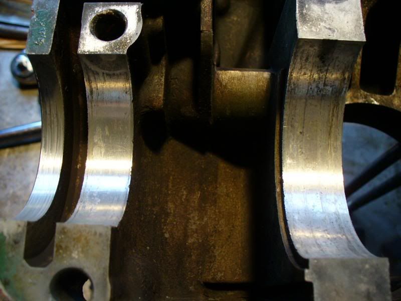
The "gap" I mentioned was when putting a straight edge across no's #1,#2,#3 mains #1 & #3 were flush but on #2 I could just get a 5 thou feeler gauge between the straight edge and either side of the saddle (not just the centre/oil way). I am guessing this is showing the case isn't quite straight.
The main reason for splitting the case was the previous owner had had it built as a turbo engine but had problems. When I bought the buggy it was in I stripped off the turbo and then found a piece of piston in the sump so decided to split the case.
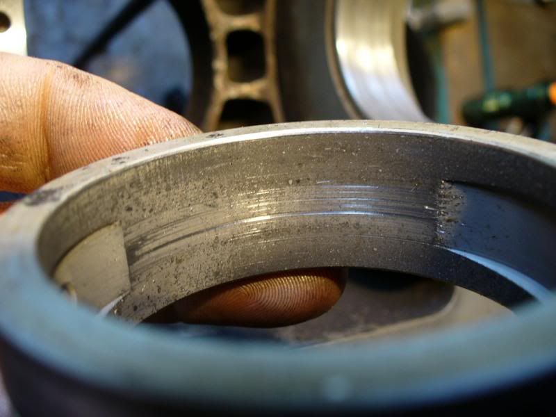
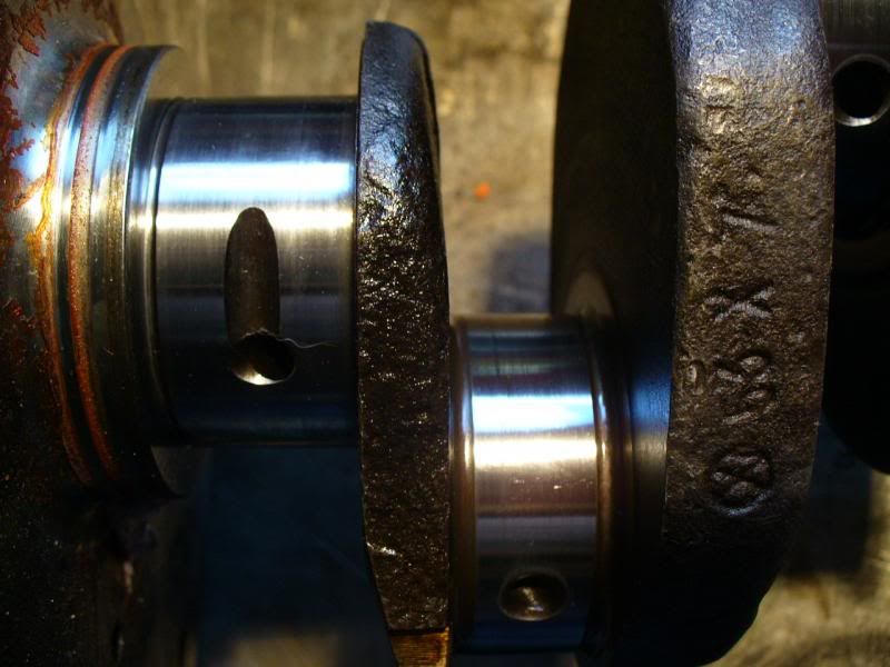
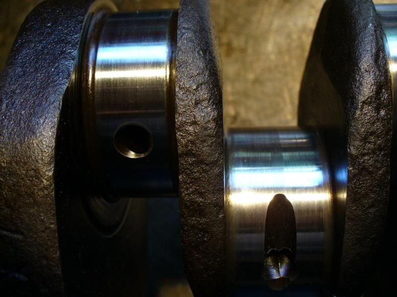
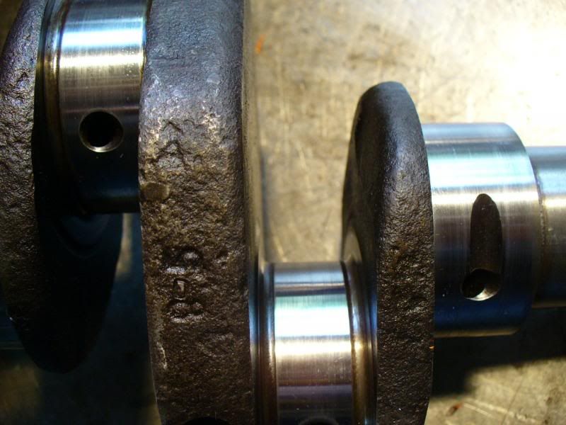
It had 3 "new" cheap P&B's and one old Mahle P&B, obviously one of the new pistons had gone pop so they had just chucked in an old B&P. As suspected the mains are showing signs of scoring from swarf in the oil ways, although the crank doesn't look to bad. Just for fun pics are below:
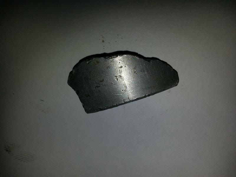
Piece of piston found in sump:
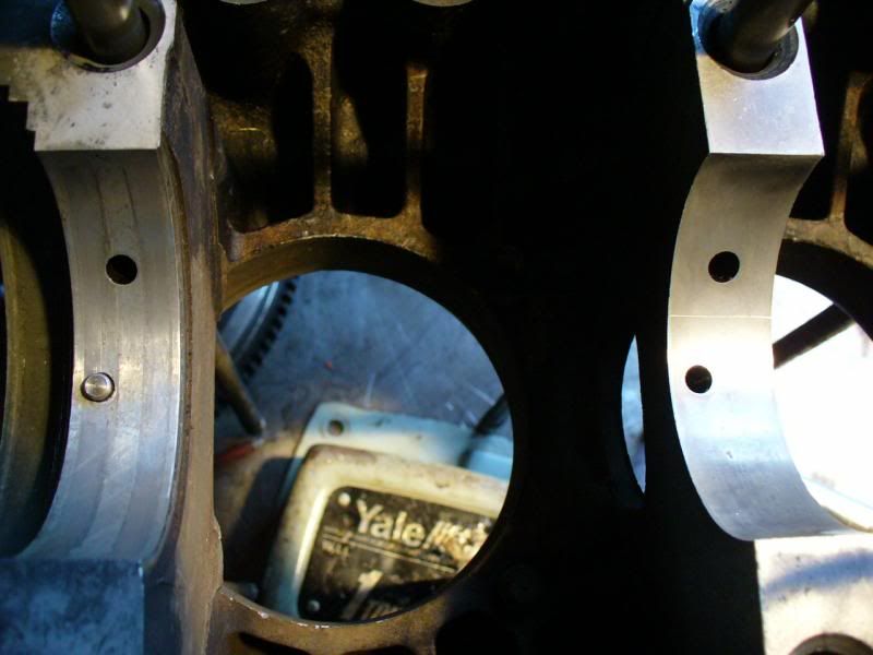
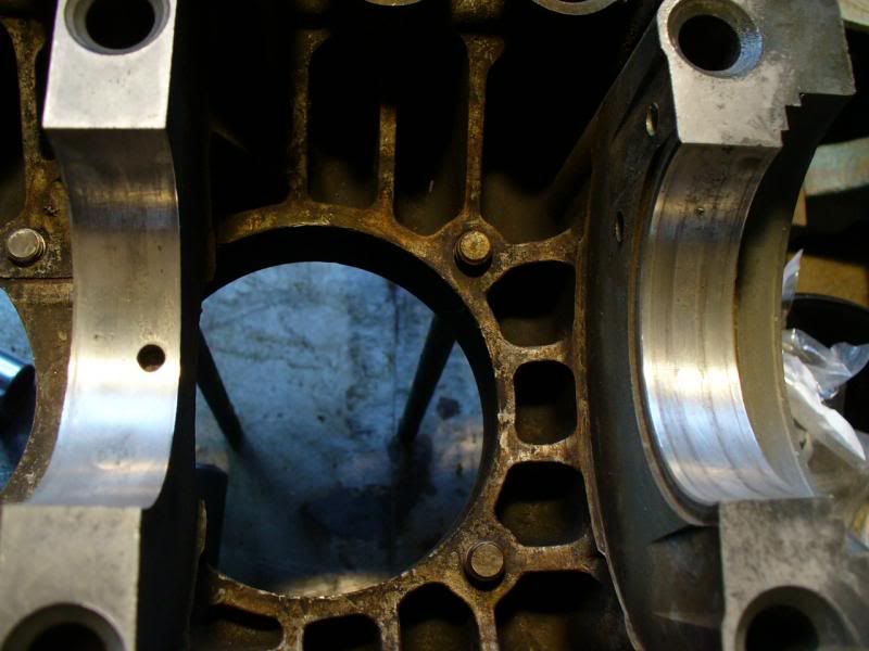
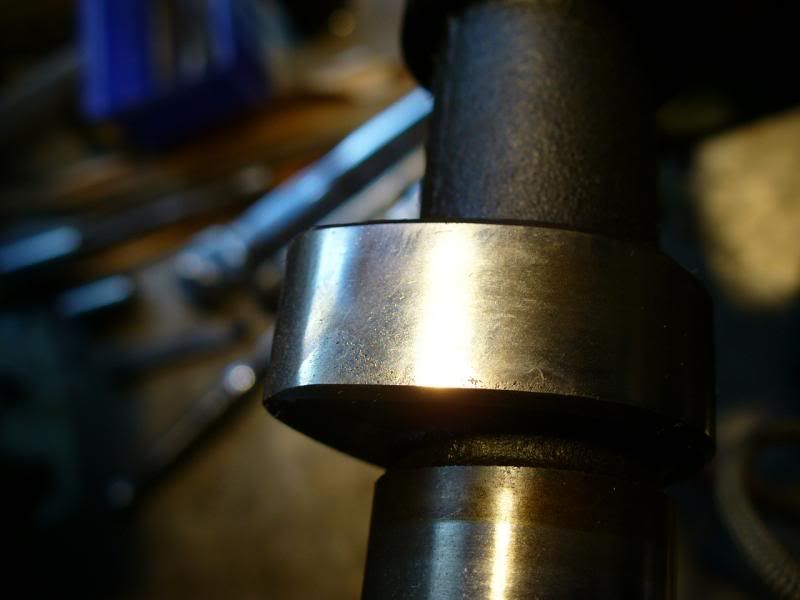
Saddle:
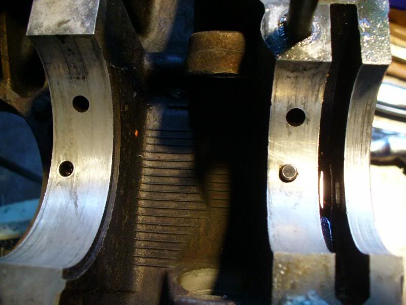
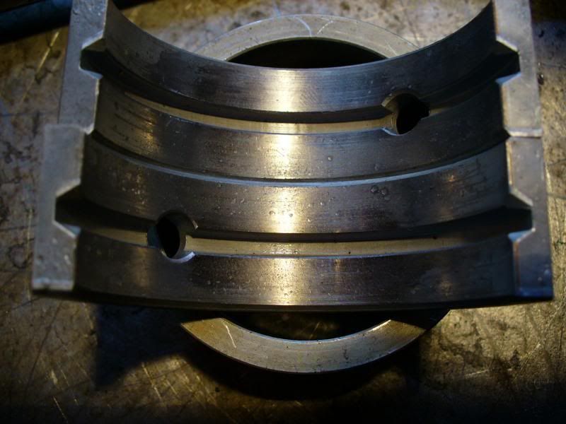
Mains:
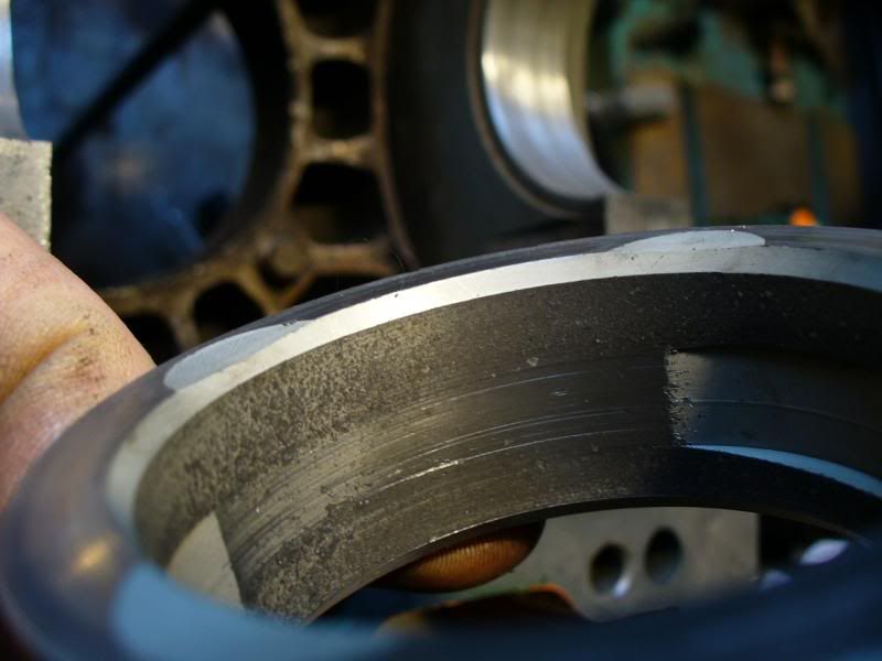
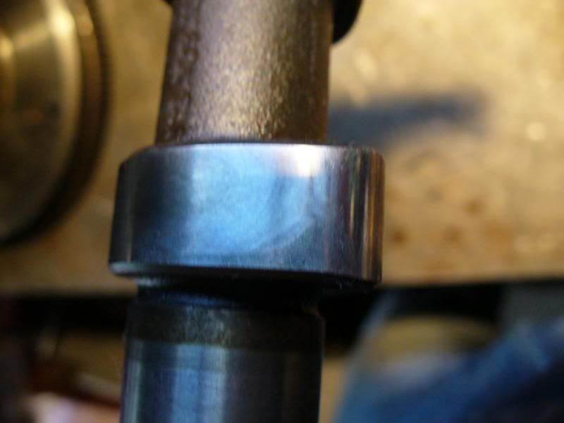
Crank:
Cam doesn't look too bad to my eye:
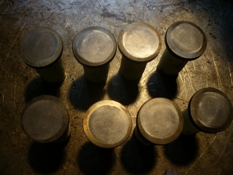
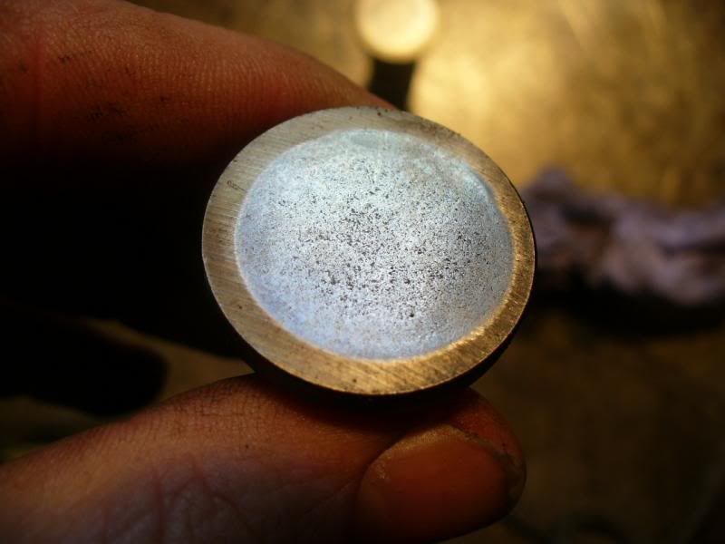
But lifters are shot:
I only need the engine to see me through the summer with low miles in the buggy, so plan is to drop in new bearings and lifters and run it like that. Thrust/end play are all ok.
Will then try to find a decent case to build up for the turbo over the summer and pop up on the forced induction forum here.
Cheers,
MM
Thanks for the info - you know how it goes sometimes when you just need to write stuff down and talk about it to make sense of it all?
So after reading your reply I thought something isn't right so went back to basics and got my calibration gear out and recalibrated my bore dial gauge. Turns out someone had dropped a couple of imperial spigots in with my metric ones so there was I thinking I was using the 65mm setting and er, I wasn't
Anyways, have now re-measured and come up with some more sensible numbers. Build sheet is below

Looks like the case has been machined a few thou tight, (measurements were taken in the horizontal plane) ovality compares these to same measurements in vertical plane.
The "gap" I mentioned was when putting a straight edge across no's #1,#2,#3 mains #1 & #3 were flush but on #2 I could just get a 5 thou feeler gauge between the straight edge and either side of the saddle (not just the centre/oil way). I am guessing this is showing the case isn't quite straight.
The main reason for splitting the case was the previous owner had had it built as a turbo engine but had problems. When I bought the buggy it was in I stripped off the turbo and then found a piece of piston in the sump
It had 3 "new" cheap P&B's and one old Mahle P&B, obviously one of the new pistons had gone pop so they had just chucked in an old B&P. As suspected the mains are showing signs of scoring from swarf in the oil ways, although the crank doesn't look to bad. Just for fun pics are below:
Piece of piston found in sump:

Saddle:


Mains:


Crank:


Cam doesn't look too bad to my eye:


But lifters are shot:


I only need the engine to see me through the summer with low miles in the buggy, so plan is to drop in new bearings and lifters and run it like that. Thrust/end play are all ok.
Will then try to find a decent case to build up for the turbo over the summer and pop up on the forced induction forum here.
Cheers,
MM
-
Marc
- Moderator
- Posts: 23741
- Joined: Thu May 23, 2002 12:01 am
Re: Measuring case wear / line bore
I make that as a late 1972 production 65HP SAE (Euro-spec) 1600 case with relatively low miles on it. 10mm head studs with no steel inserts but it should have the "sunken" top-front #3 stud; with inserts and a second-over linebore it could very well be a decent basis for a nice motor, but for what you need now it should work as-is. The off-center wear pattern on some of those lifters looks suspect; lifter bores should probably be bushed but if they don't feel too sloppy it should be OK for a while.
-
mm289
- Posts: 18
- Joined: Sun Jan 16, 2011 12:57 pm
Re: Measuring case wear / line bore
Cheers, that's what I was hoping. Will pop down the local shop and pick up some new bearings and lifters in the morning. All the lifters are numbered so I will check the bores that the off centre ones came out of for play.
Got to sort out a thread for the bellhousing bolt that has already been inserted, but the insert has pulled out again. Might try setting a new one in with some JB Weld.
Will also check the weights on the pistons to make sure the odd one isn't too far out, then should be able to get it together in the next couple of weeks
Cheers,
MM
-
Marc
- Moderator
- Posts: 23741
- Joined: Thu May 23, 2002 12:01 am
Re: Measuring case wear / line bore
Keep in mind that you may be able to bring the piston weight into line by fiddling with the wristpin (gudgeon pin) weights. All 1500/1600 as well as 87mm and some larger bores use the same length pin, so if the shop has a tin can full of them you may be able to exchange one (or three) to get the weights "close enough". I've even balanced "sweep-the-floor" trashmos by putting a nut on the end of a bolt, grinding the points of the nut and bolt head down a little, and pressing it inside a light wristpin in order to make one heavy enough...
Do you mean one of the lower engine-to-trans studs has pulled? I don't think JB Weld will hold on something that should be drawn that tight. There are several outside thread sizes made for m10x1.5 inserts, though, perhaps you can simply go to next one up. Worst case you end up with only three holding the engine in, it certainly wouldn't be the only VW running around like that
Do you mean one of the lower engine-to-trans studs has pulled? I don't think JB Weld will hold on something that should be drawn that tight. There are several outside thread sizes made for m10x1.5 inserts, though, perhaps you can simply go to next one up. Worst case you end up with only three holding the engine in, it certainly wouldn't be the only VW running around like that
-
mm289
- Posts: 18
- Joined: Sun Jan 16, 2011 12:57 pm
Re: Measuring case wear / line bore
Lol,
yes its the female thread on the casing for the trans to engine bolt that has pulled out. It has had an insert put in before but not well so that has pulled out as well :O
I might get away with cleaning up the thread and replacing the insert, the idea of the JB weld was just to give it a bit extra bite. Otherwise I will have to try and find an oversize insert.
Cheers,
MM
-
Phil69
- Posts: 64
- Joined: Sun Apr 07, 2013 4:24 am
Re: Measuring case wear / line bore
Depending on which side of the case the stud is located you may get away with a larger insert.
As Marc has said there are plenty of old bugs and buses running around with three fixings.
I've even pulled engines that have been running two! :O
As Marc has said there are plenty of old bugs and buses running around with three fixings.
I've even pulled engines that have been running two! :O
-
mm289
- Posts: 18
- Joined: Sun Jan 16, 2011 12:57 pm
Re: Measuring case wear / line bore
Its in the l/h case (cyl 1-2) lower stud.
Already had a 10mm timesert insert put in which is pulled out. Reckon their is just enough meat to get a 12mm insert in, might then turn down the other end on the lathe and thread for 10mm so it fits through the bellhousing hole.......
MM
Already had a 10mm timesert insert put in which is pulled out. Reckon their is just enough meat to get a 12mm insert in, might then turn down the other end on the lathe and thread for 10mm so it fits through the bellhousing hole.......
MM
-
mm289
- Posts: 18
- Joined: Sun Jan 16, 2011 12:57 pm
Re: Measuring case wear / line bore
Out of interest guys, whats the acceptable difference in size between piston and cylinder when measured in the same axis and position i.e. 90 deg to pin above and below rings.
Also how much wider is the skirt normally than the piston when measured under the oil ring?
Was measuring up the pistons and jugs before re-assembly and not happy with them, looks like at least one has overheated which would be in keeping with why I found a bit of skirt in the sump from the piston that had let go previously.
Probs gonna put a new set of pistons and cylinders in anyway but interested in the acceptable tolerances.
Cheers,
MM