I keep getting asked why all of this silliness, just use the truss kit and rely on the "hook" at the end of the torsion tube. That would be OK but I choose look at things a bit differently.
This is another view of the "hook" end of the torsion tube. It is marginally fine in a direct hit in that area of the torsion tube but not from the "frame"/pickle forks ends.
This shows what I am pretty sure can happen. If the applied load comes from the torsion bar end of the tube, the tube will want to lift up which would be fine but there is most likely going to be somewhat of an arc in there that pivots around the torsion tube itself. If the load comes from the bump of the trailing arm's bump stop to the bump stop pad on the shock tower then the arc forward is going to be more pronounced. If the load comes in from the "frame" the loading is going to be more of an arc forward.
The torsion "hook" is more or less welded to the thin sheet metal of the pan and it isn't that great and the material isn't that strong but, unless the hook breaks, the load should be more or less OK assuming it isn't too great. I don't think it is going to be of that much help when the arc is in motion. By adding the piece that I am trying to come up with (and the truss bar design) with the piece being mounted on the opposite side of the tube it should help support the "hook" and pan especially if there really is an arc.
Based on the one accidental drop I took years ago where I bottomed out the suspension very hard, it is that which drove the change in shock, adding a body lift, changing the preload up a bit and some more changes. Add to that: after seeing what can happen to the frame ends when the torsion tube is fully attached to the tubes of a rail that had a hard landing; e.g., the engine and transaxle dragging the ground after that hard landing or drop, I think that both this reinforcement of the torsion assembly and the truss change I am looking at should help.
Again, I don't think Dr. Porsche and his engineers intended his "peoples' car" to be used like we do.
Ol'fogasaurus black buggy
-
Ol'fogasaurus
- Posts: 17758
- Joined: Mon Nov 13, 2006 10:17 pm
Re: Ol'fogasaurus black buggy
You do not have the required permissions to view the files attached to this post.
-
Ol'fogasaurus
- Posts: 17758
- Joined: Mon Nov 13, 2006 10:17 pm
Re: Ol'fogasaurus black buggy
I got the holes in the body lift and pan re-drilled today. I originally was going to slot all three of them but, after looking at the above picture I had forgotten about the localized doublers added (the picture is a bit deceiving as it looks like the whole area is flat but it is not) to the pan half kit (its been so many years since I had done this part that I had forgotten about them. The "hook" of the torsion tube is on the bent flat/parallel to the ground area while the two doublers with threaded holes are on the sloped area of the rear cross-pieces. The off-set in the holes on the driver's side pan and body lift are aligned fairly close to being in line with the upper body lift holes but on the passenger side for some reason the off-set a bit more that the lower one was.
So.... I decided to go to one drill bit larger and do a straight drill through as the wholes in the body lift were parallel to each other. The drill through was easy but it took one drill sharpening to get the upper hole in the passenger side to drill out (remember, drilling in wood is one speed and the drilling in metal is a slower speed). The other holes all were close enough that the off-set wasn't that hard to do but the drill had to be going fast enough for the flutes not to catch on the edge of the old hole to stop and spin you around the pan a couple of time before you could let go of the trigger
 . The one hole was close to a new hole in the pan's cross-piece. Now I have to go up and grind the left over high spots where the threads were flat. The body mount bolt is now a very close but not tight fit all the way through and the head of the bolt sits flat on the body lift.
I was going to add a piece of 1" square tubing to work as a doubler but I think I won't have to because of the thickness of the doublers in the cross-piece and the thickness of the body lift.
So.... I decided to go to one drill bit larger and do a straight drill through as the wholes in the body lift were parallel to each other. The drill through was easy but it took one drill sharpening to get the upper hole in the passenger side to drill out (remember, drilling in wood is one speed and the drilling in metal is a slower speed). The other holes all were close enough that the off-set wasn't that hard to do but the drill had to be going fast enough for the flutes not to catch on the edge of the old hole to stop and spin you around the pan a couple of time before you could let go of the trigger
I was going to add a piece of 1" square tubing to work as a doubler but I think I won't have to because of the thickness of the doublers in the cross-piece and the thickness of the body lift.
You do not have the required permissions to view the files attached to this post.
-
Ol'fogasaurus
- Posts: 17758
- Joined: Mon Nov 13, 2006 10:17 pm
Re: Ol'fogasaurus black buggy
Spent the morning trying to find parts to finish the Truss bar but so far all I came up with is a big bill and that the commercial truss bar isn't all it's cracked up to be. For example: I found metric fasteners going through SAE holes (close fit but not that good for what it is supposed to do) and the tube the spherical rod ends go into isn't really strong enough wall thickness size anyway.
I spent ~$150 on the Truss setup and so far today I spent about $6 short of that in replacement (I didn't want to destroy the kit as someone else in the family can use it for light weight riding) parts and that didn't include the tubing. One interesting thing I did find out was that the color of the Nyloc style of locking nuts tells you where in the world they come from. For instance, the ones I have in the kit and some of the ones I have had before that scared the puddin' out of me as the material crumbled were blue which means they came from India.
After a long night I decided to change what I am doing a bit. Some of the cuts that would have to be made in the square tubing, while it could be done, were very complicated. I also had an epiphany during the night and I am going to change things back to something I originally tried but seeing that the kit diagonal was going to be too long and too much thread was hanging out I had given it up. No real change the cross-piece between the shock towers other than maybe going to the slightly thicker and not as tall 1 X 2 tube and go back to a mix of the tube and joining the motor mount to the tube using spherical rod ends but using a thicker and a couple inches longer tube for the diagonals. It gets the geometry a bit better this way and will stay farther away from the inboard CV boots.
I did buy two 1/2 X 20 LS @ RH taps today. Where I tried to get some of the proper tube at didn't have any in stock and I would have to buy a 20' piece to get what I wanted. The recommended thickness is 3/4 X .150 wall tube. That will give me enough "meat" for threading.
This is just a throw together look and something to peruse ("Examine or consider with attention and in detail") about. The bracket will be more stout and wider (fan shaped?) to spread the loads out more. I think I will put the spreaders tube's join weld in front to allow the bracket to also act as a doubler over the welded joint.
The cross-piece/spreader will also act as one mounting leg of the fuel tank so that is about another 80#s shared pounds of shared load on the spreader shared with the motor mount (at this time). I may end up adding a "strong back" to the spreader and diagonals to the tank mount.
This is a look at the CV boot and the diagonal roughly in place. Notice the angle of the mounting bracket is not right and the bolt is not snugged up but the distance is going to be just about an inch at full hang and not much, if any, less at full compression.
More than you wanted to know I think.
Lee
You do not have the required permissions to view the files attached to this post.
-
bajaherbie

- Posts: 9959
- Joined: Sat Jul 15, 2006 7:07 pm
Re: Ol'fogasaurus black buggy
My oldest brother broke his arm using a drill press while wearing an un-buttoned long sleeved shirt.... I can still see him walking to the house holding his S shaped arm!
Sent from my SM-G920R4 using Tapatalk
Sent from my SM-G920R4 using Tapatalk
Of all the paths you take in life, make sure a few of them are dirt.
-
Ol'fogasaurus
- Posts: 17758
- Joined: Mon Nov 13, 2006 10:17 pm
Re: Ol'fogasaurus black buggy
Playing around with how things are sitting right now I can go from a 9" long rod to ~ (roughly) a 10" to almost an 11" rod. That is tightening things up on the existing diagonal assy and measuring. If the spherical rod ends where longer and fully threaded then the 9" tube would work but the exposed threaded areas are not properly supported and there isn't enough left in the tube to give strength also.
I was advised to try McMaster Carr to fine the proper rod length but I couldn't find it. Still looking around did find some but don't recognize the company so unsure Need ~4'.
I was advised to try McMaster Carr to fine the proper rod length but I couldn't find it. Still looking around did find some but don't recognize the company so unsure Need ~4'.
-
Ol'fogasaurus
- Posts: 17758
- Joined: Mon Nov 13, 2006 10:17 pm
Re: Ol'fogasaurus black buggy
I had something similar which is why the drill jig use and clamps. Mine wasn't as bad but I did ruin a good, very used, slip over the head but baggy sweat shirt.bajaherbie wrote: ↑Fri Dec 08, 2017 3:36 pm My oldest brother broke his arm using a drill press while wearing an un-buttoned long sleeved shirt.... I can still see him walking to the house holding his S shaped arm!
Sent from my SM-G920R4 using Tapatalk
-
dustymojave
- Posts: 2312
- Joined: Mon Dec 01, 2008 9:08 pm
Re: Ol'fogasaurus black buggy
Just for your perusal Lee:
This is in my 58 Baja.
Pardon the spider webs and other indications that it's not entirely a show car.
Pardon the spider webs and other indications that it's not entirely a show car.
You do not have the required permissions to view the files attached to this post.
Richard
Lake LA, Mojave Desert, SoCal
Speed Kills! but then...So does OLD AGE!!
Tech Inspection: SCCA / SCORE / HDRA / ARVRA / A.R.T.S. OffRoad Race Tech - MDR, MORE, Glen Helen BajaCup
Retired Fabricator
'58 Baja with 955K Miles and counting
Lake LA, Mojave Desert, SoCal
Speed Kills! but then...So does OLD AGE!!
Tech Inspection: SCCA / SCORE / HDRA / ARVRA / A.R.T.S. OffRoad Race Tech - MDR, MORE, Glen Helen BajaCup
Retired Fabricator
'58 Baja with 955K Miles and counting
-
Ol'fogasaurus
- Posts: 17758
- Joined: Mon Nov 13, 2006 10:17 pm
Re: Ol'fogasaurus black buggy
Thanks Dusty, I was hoping for input from you, 'Pile, Marc plus all the others.
I had thought about doing just what you have shown (minus the hole in the center which is a really good idea for sand and mud drainage) which is what the one guy I was talking about a while back who was (supposedly) a factory trained VW mechanic. I mentioned that he said that VW (again supposedly) thought that adding several additions to support the "hook's" loading should be done; especially when you are using the bug for other than daily transportation and maybe even then (unless you are going for concourse points that is). After those two sudden unplanned drops when the crest of a dune suddenly gave way and I landed so hard I suddenly got "religion" on additional support for the torsion tube to pan anyway .
.
Add to that that I am not that good of a welder especially after learning (self taught) how to after retirement and not doing it that much over the years either. I also wanted to not only tie the cage into the mess by using the body lift which I thought was better than drilling a couple of holes through the body to make the connection to the torsion tube. I also wanted loading from both underneath and above so yes, I am probably doing overkill. If you sit in engineering design review meetings (especially when they are at your desk) where the combatants can get loud at times, you hear a lot of the reasoning on things which hang in the back of your mind for 50 years or so  . If you see a lot of "broken" toys being loaded up on a trailer or being drug back to camp busted you look and also listen.
Marc also made the input a while back on reinforcing the seat tracks with doublers and U-bolts which VW had put out. They all add up to change thinking.
After almost 25 years "on the board" (e.g., drafting tables which also includes CAD) then 9 years of either teaching and/or checking/mentoring other's work I am so use to high "G" ratings (3Gs, then 9Gs, finally12G and then often with a "crib" that takes the loads being designed up to 16G) in design which I still carry that with me. I also have seen (some of it mine) a lot of failures from both Hot Rodding and off-roading so that I am a bit on the careful side. A lot of people I have known have not made it to my age because of not thinking things out well .
.
Thanks again for the input and I always value yours and everybody else's ideas. If I am going into to much detail let me know and I will back off.
Lee
Oh, and I don't think I can weld the mounts to in place until I add/account for the seal between the pan and the body lift as things are probably going to be a tight bolt up.
Oh, and the temperature around just went up to 28° .
I had thought about doing just what you have shown (minus the hole in the center which is a really good idea for sand and mud drainage) which is what the one guy I was talking about a while back who was (supposedly) a factory trained VW mechanic. I mentioned that he said that VW (again supposedly) thought that adding several additions to support the "hook's" loading should be done; especially when you are using the bug for other than daily transportation and maybe even then (unless you are going for concourse points that is). After those two sudden unplanned drops when the crest of a dune suddenly gave way and I landed so hard I suddenly got "religion" on additional support for the torsion tube to pan anyway
Add to that that I am not that good of a welder especially after learning (self taught) how to after retirement and not doing it that much over the years either. I also wanted to not only tie the cage into the mess by using the body lift which I thought was better than drilling a couple of holes through the body to make the connection to the torsion tube. I also wanted loading from both underneath and above so yes, I am probably doing overkill. If you sit in engineering design review meetings (especially when they are at your desk) where the combatants can get loud at times, you hear a lot of the reasoning on things which hang in the back of your mind for 50 years or so
Marc also made the input a while back on reinforcing the seat tracks with doublers and U-bolts which VW had put out. They all add up to change thinking.
After almost 25 years "on the board" (e.g., drafting tables which also includes CAD) then 9 years of either teaching and/or checking/mentoring other's work I am so use to high "G" ratings (3Gs, then 9Gs, finally12G and then often with a "crib" that takes the loads being designed up to 16G) in design which I still carry that with me. I also have seen (some of it mine) a lot of failures from both Hot Rodding and off-roading so that I am a bit on the careful side. A lot of people I have known have not made it to my age because of not thinking things out well
Thanks again for the input and I always value yours and everybody else's ideas. If I am going into to much detail let me know and I will back off.
Lee
Oh, and I don't think I can weld the mounts to in place until I add/account for the seal between the pan and the body lift as things are probably going to be a tight bolt up.
Oh, and the temperature around just went up to 28°
-
dustymojave
- Posts: 2312
- Joined: Mon Dec 01, 2008 9:08 pm
Re: Ol'fogasaurus black buggy
I am not only recommending the plate from torsion housing to back edge of pan that I posted above, I also approve of your brace from torsion housing to lift...AND I'm also recommending some bracing from cage to at least the upper rear shock mount.
That latter can be brace tubes that theoretically pass through the body fiberglass. The brace tubes would be interrupted at the 'glass with 3/16 thick sandwich plates with at least (4) 3/8" bolts per junction. The bolts would be all that would pass through the 'glass.
This would brace the pan, the torsion housing, the shock mount, the engine/trans mounts and yokes, and the roll bar/cage. Oh, and the body shell too. Think of the overall structure Lee, not just each component part.
That comment you quoted above
If the picture of the lower side of the torsion housing end and hook shown above is your pan for this black buggy,
download/file.php?id=20387
Shop Talk doesn't want to copy that image here - Shoot FIRE! It ain't as if I'm stealing a copyrighted work, just referring back to it in this same thread for informational purposes so folks know which picture I mean.
then it would have been simpler to have added a diagonal tube underneath welded to the pan edge reinforcement and to the bottom of the torsion housing end forging (it's NOT a casting) under the bushing area between the cover plate bolt bosses.
But still the roll bar brace is something I recommend for the reasons stated above in this post.
That latter can be brace tubes that theoretically pass through the body fiberglass. The brace tubes would be interrupted at the 'glass with 3/16 thick sandwich plates with at least (4) 3/8" bolts per junction. The bolts would be all that would pass through the 'glass.
This would brace the pan, the torsion housing, the shock mount, the engine/trans mounts and yokes, and the roll bar/cage. Oh, and the body shell too. Think of the overall structure Lee, not just each component part.
That comment you quoted above
, that you get from other people shows that they are street Bug or fiberglass buggy people, not real offroaders. They don't understand the forces or have experience of durability issues.why all of this silliness, just use the truss kit and rely on the "hook" at the end of the torsion tube
If the picture of the lower side of the torsion housing end and hook shown above is your pan for this black buggy,
download/file.php?id=20387
Shop Talk doesn't want to copy that image here - Shoot FIRE! It ain't as if I'm stealing a copyrighted work, just referring back to it in this same thread for informational purposes so folks know which picture I mean.
then it would have been simpler to have added a diagonal tube underneath welded to the pan edge reinforcement and to the bottom of the torsion housing end forging (it's NOT a casting) under the bushing area between the cover plate bolt bosses.
But still the roll bar brace is something I recommend for the reasons stated above in this post.
Richard
Lake LA, Mojave Desert, SoCal
Speed Kills! but then...So does OLD AGE!!
Tech Inspection: SCCA / SCORE / HDRA / ARVRA / A.R.T.S. OffRoad Race Tech - MDR, MORE, Glen Helen BajaCup
Retired Fabricator
'58 Baja with 955K Miles and counting
Lake LA, Mojave Desert, SoCal
Speed Kills! but then...So does OLD AGE!!
Tech Inspection: SCCA / SCORE / HDRA / ARVRA / A.R.T.S. OffRoad Race Tech - MDR, MORE, Glen Helen BajaCup
Retired Fabricator
'58 Baja with 955K Miles and counting
-
dustymojave
- Posts: 2312
- Joined: Mon Dec 01, 2008 9:08 pm
Re: Ol'fogasaurus black buggy
That blue painted tube in my picture of the torsion housing brace plate is my lower torsion housing brace coming back from the bottom of the B pillar. Since your pan has the tube brace in the body bolt channel, that diagonal I mentioned above would take the place of my blue tube.
Richard
Lake LA, Mojave Desert, SoCal
Speed Kills! but then...So does OLD AGE!!
Tech Inspection: SCCA / SCORE / HDRA / ARVRA / A.R.T.S. OffRoad Race Tech - MDR, MORE, Glen Helen BajaCup
Retired Fabricator
'58 Baja with 955K Miles and counting
Lake LA, Mojave Desert, SoCal
Speed Kills! but then...So does OLD AGE!!
Tech Inspection: SCCA / SCORE / HDRA / ARVRA / A.R.T.S. OffRoad Race Tech - MDR, MORE, Glen Helen BajaCup
Retired Fabricator
'58 Baja with 955K Miles and counting
-
Ol'fogasaurus
- Posts: 17758
- Joined: Mon Nov 13, 2006 10:17 pm
Re: Ol'fogasaurus black buggy
I did this a long time ago but this is the 1" square tube I added in the pans body mount tunnel. At the advice of hotrodsurplus (I think that was his name) I added crush sleeves in the holes. Basically crush tubes are lengths of tube between the upper and lower walls of the square tube instead of raw holes for the body bolts to go through that can allow salt water and sand in the tube. Boy, was that a chore. All part of the those now missing Photobucket photos. I was going to do the same thing to the rear cross diagonals but the doublers that were there became a problem as I would have to do some "hinky" mods to the 1" square doublers or cut the top of the cross piece out to remove the doublers then make new sections to fill the removed voids.
"I am not only recommending the plate from torsion housing to back edge of pan that I posted above, I also approve of your brace from torsion housing to lift...AND I'm also recommending some bracing from cage to at least the upper rear shock mount.
That latter can be brace tubes that theoretically pass through the body fiberglass. The brace tubes would be interrupted at the 'glass with 3/16 thick sandwich plates with at least (4) 3/8" bolts per junction. The bolts would be all that would pass through the 'glass.
This would brace the pan, the torsion housing, the shock mount, the engine/trans mounts and yokes, and the roll bar/cage. Oh, and the body shell too. Think of the overall structure Lee, not just each component part.
The doubler to connect to the down tubes through the f-glass is something I thought about but since this is not an older style thick glass body but a thin S-glass body I have had reservations. This is one of the reasons for the upper connection of the body lift (0.095 wall) to the torsion tube that would back up the down tube of the cage that would be connected to the body lift.
It is the same for the upper tubes in front that hold the top of the beam then connect to the front hoop of the cage Not saying "no" but I have and still will think about it. Not too far along to change things yet.
The same with the shock tower, right now it has a lot of things going on it like the bracketry for the fuel tank. Since I am a bit leery on just how strong the shock towers are after seeing so many of them broken out on the dunes when bottoming out the shocks and shocking the tower to pieces , even if I "boxed" them, so I have been reticent about using them for the cage (which is way off still). If my cage builder is still alive (he is a bit younger than I am and has been retired for several years. He also used to build sand buggies for dune ride places [$$$], and cages for race cars.) I will talk to him about it also.
Good input and I will heavily consider it.
Lee
"I am not only recommending the plate from torsion housing to back edge of pan that I posted above, I also approve of your brace from torsion housing to lift...AND I'm also recommending some bracing from cage to at least the upper rear shock mount.
That latter can be brace tubes that theoretically pass through the body fiberglass. The brace tubes would be interrupted at the 'glass with 3/16 thick sandwich plates with at least (4) 3/8" bolts per junction. The bolts would be all that would pass through the 'glass.
This would brace the pan, the torsion housing, the shock mount, the engine/trans mounts and yokes, and the roll bar/cage. Oh, and the body shell too. Think of the overall structure Lee, not just each component part.
The doubler to connect to the down tubes through the f-glass is something I thought about but since this is not an older style thick glass body but a thin S-glass body I have had reservations. This is one of the reasons for the upper connection of the body lift (0.095 wall) to the torsion tube that would back up the down tube of the cage that would be connected to the body lift.
It is the same for the upper tubes in front that hold the top of the beam then connect to the front hoop of the cage Not saying "no" but I have and still will think about it. Not too far along to change things yet.
The same with the shock tower, right now it has a lot of things going on it like the bracketry for the fuel tank. Since I am a bit leery on just how strong the shock towers are after seeing so many of them broken out on the dunes when bottoming out the shocks and shocking the tower to pieces
Good input and I will heavily consider it.
Lee
You do not have the required permissions to view the files attached to this post.
-
Ol'fogasaurus
- Posts: 17758
- Joined: Mon Nov 13, 2006 10:17 pm
Re: Ol'fogasaurus black buggy
Dusty, I've done so many drawings in my working life I can do a lot of this in my head. I have tried to show what I see in my head via modifying a couple of pictures.
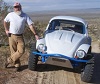
This is a picture of my black buggy with me in it. I approximated the cage as it likely might be. In my black buggy I am sitting about 3" above the floor which ends up sitting one farther back on the pan than one might sit in stock sitting arrangement. The seat back is pretty even with the second bend on the pan which is where the rear of the door would be in a bug. Also, in this body there isn't really any room for a rear although there is a FG piece for it but it is not a good idea to have that seating arrangement off-road.
(in my blue buggy I am sitting 1/2" off the pan floor and sitting almost to the rear cross-piece. the rear hoop on the cage is mounted on the corner of the pan and the rear cross-piece. The down bars go to the center of the tray behind the seats and connect to that cross-piece that they used to add under the tray that goes between the shock towers This is an 80' wheel base which makes things even tighter) The first shot was an approximation of seat location which I am still fighting with. The rear cross piece sits just in front of the rear fender.
This is a bit more hokey but it should give an approximation of the down bars from the cage. Awfully close to the body lift... if it doesn't touch it. That is why I am futzing with the additional support for the torsion tube and am tying it to the 0.095 wall body lift and through it to the torsion tube. Not the best of ideas but still working on ways around it.
You do not have the required permissions to view the files attached to this post.
-
Ol'fogasaurus
- Posts: 17758
- Joined: Mon Nov 13, 2006 10:17 pm
Re: Ol'fogasaurus black buggy
", that you get from other people shows that they are street Bug or fiberglass buggy people, not real offroaders. They don't understand the forces or have experience of durability issues."
You are very correct here Dusty. One of the things people don't think of is that the FG bodies do not add much, if any, support structure to the pan; mainly it is the missing roof which is so important to spreading loads around the whole pan and body unit as a whole. While they look cool especially out on the dunes but they are now getting very rare to see even on the street and I am seeing less and less of them up for sale and the ones I do see are either way over priced or a POS.
Also, glass bodies are usually a "one shot deal" when it comes and to roll-overs or any kind of solid body hit; some can be fairly easy to patched up others it takes more... if possible, work. I did hear of one incident where the guy somehow "hooked" the wheels, it flipped, bounced on the cage then back on the wheels w/o touching the body but that is very rare indeed and I sure would be looking at the body carefully for stress cracks . My Model T style of buggy is even more susceptible to just bouncing around because of the "wing" style of fenders. I still have to bolster them up to keep them from bouncing around and cracking the gel coat or cracking the fender join to the body.
The front fencers are going to be the worse with the rear fenders not out of danger especially with the Model A tail lights I have for them. If I ever get it finished it is sure going to look cool out on the dunes. Right now it is being used to keep my mind active.
You are very correct here Dusty. One of the things people don't think of is that the FG bodies do not add much, if any, support structure to the pan; mainly it is the missing roof which is so important to spreading loads around the whole pan and body unit as a whole. While they look cool especially out on the dunes but they are now getting very rare to see even on the street and I am seeing less and less of them up for sale and the ones I do see are either way over priced or a POS.
Also, glass bodies are usually a "one shot deal" when it comes and to roll-overs or any kind of solid body hit; some can be fairly easy to patched up others it takes more... if possible, work. I did hear of one incident where the guy somehow "hooked" the wheels, it flipped, bounced on the cage then back on the wheels w/o touching the body but that is very rare indeed and I sure would be looking at the body carefully for stress cracks
The front fencers are going to be the worse with the rear fenders not out of danger especially with the Model A tail lights I have for them. If I ever get it finished it is sure going to look cool out on the dunes. Right now it is being used to keep my mind active.
You do not have the required permissions to view the files attached to this post.
-
Ol'fogasaurus
- Posts: 17758
- Joined: Mon Nov 13, 2006 10:17 pm
Re: Ol'fogasaurus black buggy
I was able to find two, 1' long pieces of 3/4 X 0.156 wall round stock today. They won't be in for a few days but we have a couple of very important thing to do so I will be able to pick the tubing up Monday. This will now allow me to make patterns in order the proper size of 3/16" flat stock for the mounts now that I know I can continue on with this design. For the mounts I am using the same size material as came in the Truss Bar assembly I bought.
As near as I can tell w/o the mounts being in place the new rod will have to be about 10" or 10"+ long vs. the 9" the kit had. This is to get a lot of threads being used internally and not so much being put under load with the shorter tubes. The jam nuts were also interesting: in the kit the jam nuts were .44 thick where the jam nuts I got were .31 for the right hand thread and the left hand thread were .43. The price of the RH threaded rod end was a lot cheaper than the left hand thread rod end as I was told that they sell more RH threaded things than LH threaded things. The same for the jam nuts, the sell more RH jam nuts than LH jam nuts so the don't stock the thinner jam nuts (I bought this at a regular fastener store not a "box store")
If any one is interested in the pattern making process let me know so I can post pictures on how I attacked it otherwise I will just do it and show the finished parts.
I also am thinking about adding a doubler to the top of the 1 X 2 rectangular tube in order to use it to make more structure for the rear upright for the fuel tank mount. I think it will also help the tube in the push/pull loads that can be had on bad landings and bumps to the bottom of the frame horns (hopefully there will be none!). The 1" X 1/8th inch wall tube fits perfectly to the bend in the rectangular tube.
-
Ol'fogasaurus
- Posts: 17758
- Joined: Mon Nov 13, 2006 10:17 pm
Re: Ol'fogasaurus black buggy
If I get a chance, I am going to try to fit the 1 X 2 in place tomorrow and see what it looks like compared to the 1 X 3 and looking at the mounting of each to the shock tower. The wall thickness of the 1 X 2 is a bit thicker that the 1 X 3 while the draw down (the long side) will be shorter than that with the 1 X 3 plus I want to check to see if there is any and if so how much the flexing will be between the two tubes. I was concerned with the basics before so I didn't get to look at the other more important things. I think either tube should be OK but I am going to add the angle iron doubler to the upper (forward) corner of the tube of my choice anyway. Better safe than sorry.
I did some measuring and the fuel tank mounting brackets will be slightly inboard of the two Truss bar's mounting brackets. The rear of the fuel tank's mounting will have to be positioned off the to of the solid engine mount and splay out at a shallow angle. This is so the mounting brackets on the tank can be located as close to the ends as possible. With them too close together then any "sloshing" of the fuel in the tanks can be not the best one would want. Bracing will be needed. Most pf these fuel tanks don't have baffles inside so, lets say, you suddenly when climbing a steep dune you suddenly turn to run across the face of the dune and the fuel will try to climb because of the sharp turn then slosh to the down hill side of the tank sometimes with a heavy hand; not an easy flow (if that makes sense).
I did some measuring and the fuel tank mounting brackets will be slightly inboard of the two Truss bar's mounting brackets. The rear of the fuel tank's mounting will have to be positioned off the to of the solid engine mount and splay out at a shallow angle. This is so the mounting brackets on the tank can be located as close to the ends as possible. With them too close together then any "sloshing" of the fuel in the tanks can be not the best one would want. Bracing will be needed. Most pf these fuel tanks don't have baffles inside so, lets say, you suddenly when climbing a steep dune you suddenly turn to run across the face of the dune and the fuel will try to climb because of the sharp turn then slosh to the down hill side of the tank sometimes with a heavy hand; not an easy flow (if that makes sense).
Lee
My opinion is worth slightly less than what you paid for it.
My opinion is worth slightly less than what you paid for it.