I'm in the process of getting the wiring harness sorted for my MS2 into a 57 T1 project and am wondering if I should set up the harness to go with the engine during engine removal or stay with the chassis, or split through a bulk head connection. Any ideas I can implement now to save me grief later would be most appreciated as the body/pan are still apart, and pics are always welcomed.
The current plan is to have the ecu and relay board mounted under the rear seat and am debating on having the harness fed through the now defunct heater channel or feed it up into the normal body cavity (where the LHD harness would typically go) and down inside the rear quarter.
Scenario 1 means issues with engine install/removal without an extra connection in the harness (potential for voltage drop/connector/sensor issues)
Scenario 2 includes potential damage to the harness from pulling through over sharp edges and strange angles for the vac line for map sensor.
How have you setup your engines harness?
-
Marc
- Moderator
- Posts: 23741
- Joined: Thu May 23, 2002 12:01 am
Re: How have you setup your engines harness?
For the low-current wires you might consider a military-grade junction (assuming there's a surplus outlet nearby - they're pretty spendy retail).
"Amphenol" is the supplier of choice for US Navy connectors, RAN probably uses them too. Not the easiest to make up initially - soldering required - but damn reliable. There're hundreds of configurations, here's a typical one: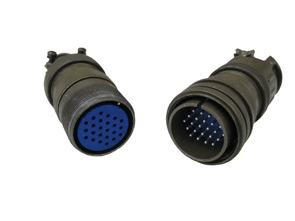
"Amphenol" is the supplier of choice for US Navy connectors, RAN probably uses them too. Not the easiest to make up initially - soldering required - but damn reliable. There're hundreds of configurations, here's a typical one:
-
Piledriver

- Moderator
- Posts: 22520
- Joined: Sat Feb 16, 2002 12:01 am
Re: How have you setup your engines harness?
You can get those in crimp with removable pins as well.
Requires the proper crimper/die.
Crimp recommended over soldering, but those can easily be built with proper strain relief, so soldering IN THAT CASE is not quite the failure waiting to happen as in automotive connectors.
They make very similar plastic industrial connectors that take the same pins but aren't fully water/nuke proof.
MUCH less spendy, even new.
BUT:
I just ran my harness through smurf tubes (with larger MS3 harness, bilge pump tube) and can unplug everything and simply tie off to side for engine R&R. I can even yank the harness back out intact. (putting it IN required serious tape off and a lead wire/fishing, out is easy)
Sorta like running wire in flex conduit, but much thinner---still provides protection etc.
Less connectors=less work, less $$$, and far less to go wrong.
KISS principle applies.
Addendum to Newtons first law:
zero vehicles on jackstands, square gets a fresh 090 and 1911, cabby gets a blower.
EZ3.6 Vanagon after that.(mounted, needs everything finished) then Creamsicle.
zero vehicles on jackstands, square gets a fresh 090 and 1911, cabby gets a blower.
EZ3.6 Vanagon after that.(mounted, needs everything finished) then Creamsicle.
-
thedrew
- Posts: 83
- Joined: Wed Apr 15, 2015 8:44 am
Re: How have you setup your engines harness?
I made a box out of some stainless sheet and tried to encapsulate everything in it and the MS3X box is mounted to the top of it.
I fabbed up some breakout boards and use Molex 5569 (Mini Fit Jr) connectors for all my connections so I can fiddle with each one easily. The board supports 3 different configurations, 1x8pin, 2x4pin, or 3x2pin.
I can easily disconnect everything and pull the whole box out if I want to.
I'm using Leash electronics relay boards, handy lil things.
the box sits in the luggage area behind the seat and i have a firewall grommet that goes into the engine compartment.
I coughed up the money for the real deal Molex crimper tool, and that makes it easy to work with and a solid connection. Been running this for a few months, no issues!
-
66brm
- Posts: 405
- Joined: Mon Apr 12, 2010 6:55 pm
Re: How have you setup your engines harness?
Thanks guys, Marc, I've seen those connectors when I was in the Army playing with the Abrams tanks, I'll have a hunt see if I can come up with some locally that will do.
Pile I'll have to Google Smurf tubes, I could get some interesting responses.....
theDrew, whoa dude thats why I went with the relay board....I think I had a mini breakdown just looking at it. But the idea of mounting the relay board behind the back seat and passing the harness through the firewall using a grommet has got me thinking, It will certainly shorten the run between the engine bay and board but will still need to run a tube for MAP back to the ECU.
I also need to research installs utilising MSD 6AL's , no sure of how much noise they make and whether I need to isolate the mount and harness for that
-
Chip Birks

- Posts: 4006
- Joined: Wed Mar 12, 2008 5:59 pm
Re: How have you setup your engines harness?
Why are you using MSD? Your MS2 will replace that box without issue.66brm wrote: I also need to research installs utilising MSD 6AL's , no sure of how much noise they make and whether I need to isolate the mount and harness for that
-
Steve Arndt
- Posts: 7404
- Joined: Sat Mar 10, 2001 12:01 am
Re: How have you setup your engines harness?
I made my own really board. Gang plugs reside under the package tray for the engine wiring. One connector for my four coils, one connector for my four injectors (coil near plug four channels, sequential injection four channels each connector), finally one connector for all my sensors.
Steve
My Baja Build
My Baja Build
-
66brm
- Posts: 405
- Joined: Mon Apr 12, 2010 6:55 pm
Re: How have you setup your engines harness?
Yeah I know, and I intend to go that way, I'm getting my head around fuel only first and running the MSD as its been sitting on the shelf for years, after the fuel is sorted then I'll probably run Mario's crank kit and the MS2 with the distributor lockedChip Birks wrote:Why are you using MSD? Your MS2 will replace that box without issue.66brm wrote: I also need to research installs utilising MSD 6AL's , no sure of how much noise they make and whether I need to isolate the mount and harness for that