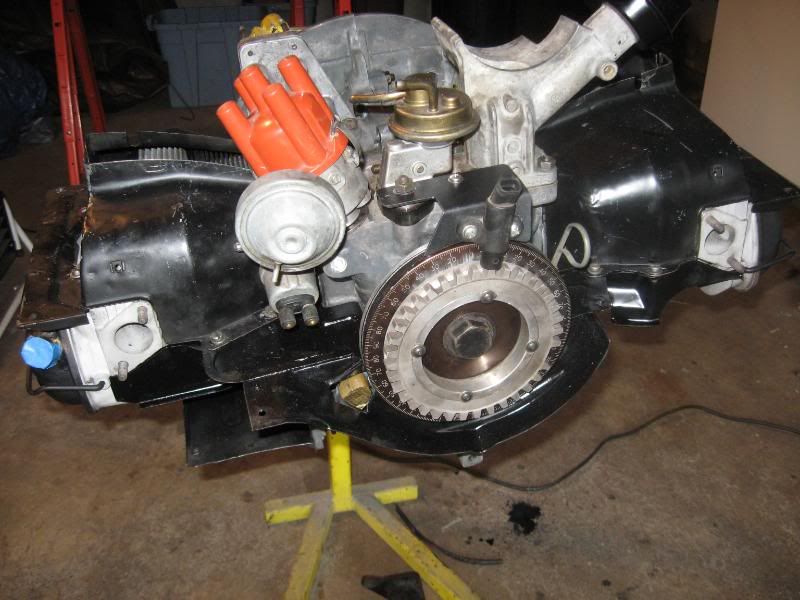
So i've drilled my flywheel as my trigger it has 36 evenly spaced drillings and i'll be using the ford EDIS sensor in the sensor hole that late cases had (just off to the right of the case parting line)
So what i want to know is which tooth do i remove? 90 degrees clockwise of the sensor but do i join it to the one before or after that mark id that makes sense?
In the picture i'll attach later, the strong points to the hole the sensor will see when the crank is at TDC on number 1, and the roll of metal is 9 after that, is that the bit i remove or...?
Thanks
Andy
PS:
T1 case
MS1 2.2 extra
EDIS
Making a trigger, which tooth to remove..?
-
andy198712
- Posts: 2433
- Joined: Wed Apr 13, 2011 1:01 pm
-
andy198712
- Posts: 2433
- Joined: Wed Apr 13, 2011 1:01 pm

-
Piledriver

- Moderator
- Posts: 22520
- Joined: Sat Feb 16, 2002 12:01 am
Re: Making a trigger, which tooth to remove..?
You are going to have to fill one of those with steel again....
I recommend SKIPPING the EDIS, and use the native MS2/3 direct fire/wheel decoder.
Then you can just basically pick one ~around 80 BTDC, and set the offset in TunerStudio.
For EDIS to work right, it has to be pretty exact.
I recommend SKIPPING the EDIS, and use the native MS2/3 direct fire/wheel decoder.
Then you can just basically pick one ~around 80 BTDC, and set the offset in TunerStudio.
For EDIS to work right, it has to be pretty exact.
Addendum to Newtons first law:
zero vehicles on jackstands, square gets a fresh 090 and 1911, cabby gets a blower.
EZ3.6 Vanagon after that.(mounted, needs everything finished) then Creamsicle.
zero vehicles on jackstands, square gets a fresh 090 and 1911, cabby gets a blower.
EZ3.6 Vanagon after that.(mounted, needs everything finished) then Creamsicle.
-
fastback

- Posts: 1670
- Joined: Wed Sep 12, 2001 12:01 am
Re: Making a trigger, which tooth to remove..?
at TDC if you have the sensor at 12 o'clock , remove the metal between the holes at 3 o'clock
you just compensate the ignition in the ignition table .
put 10 degrees in all the cells in the table, check advance with a strobe and read off at the pulley
then you have the offset ,if you read 15 degress at the pulley pull of 5 degrees in all your cells in the final table.
you just compensate the ignition in the ignition table .
put 10 degrees in all the cells in the table, check advance with a strobe and read off at the pulley
then you have the offset ,if you read 15 degress at the pulley pull of 5 degrees in all your cells in the final table.
-
andy198712
- Posts: 2433
- Joined: Wed Apr 13, 2011 1:01 pm
Re: Making a trigger, which tooth to remove..?
Piledriver wrote:You are going to have to fill one of those with steel again....
I recommend SKIPPING the EDIS, and use the native MS2/3 direct fire/wheel decoder.
Then you can just basically pick one ~around 80 BTDC, and set the offset in TunerStudio.
For EDIS to work right, it has to be pretty exact.
Seems how these are done?
and my pulley is drilled like this also with a slotted hole as the missing tooth.
i only have MS1 2.2 to work with, and loosing the EDIS module isn't as simple on that i gather (although not impossible)
Can you not set offset with EDIS in Tunerstudio so you don't have to compensate with the map?
so my sensor being a bit to the right, would i just make my missing tooth the same amount around the pulley, so the angle is still the same between the sensor and missing to tooth? IE do it at the 4:30 isn area?
Cheers Guys
Andy
-
fastback
- Posts: 1670
- Joined: Wed Sep 12, 2001 12:01 am
Re: Making a trigger, which tooth to remove..?
IIRC i did not get the trigger offset to work with edis on the earlier fimrware
that's ehy i used the offset in the table
as long as u keep the posistion between the sensor and missing tooth @ ~90 degres u can mount i anywhere.
good info here:
http://www.autosportlabs.net/Ford_EDIS_ ... nformation
that's ehy i used the offset in the table
as long as u keep the posistion between the sensor and missing tooth @ ~90 degres u can mount i anywhere.
good info here:
http://www.autosportlabs.net/Ford_EDIS_ ... nformation
-
Piledriver
- Moderator
- Posts: 22520
- Joined: Sat Feb 16, 2002 12:01 am
Re: Making a trigger, which tooth to remove..?
Inputs: use the opto with a hall sensor.(set up to suit 5v or 12v) works at zero rpm, very easy to troubleshoot.
Outputs:
To use any MS mainboard (using -extra firmware) would require 2 1k pullup resistors on the l & r led, and 2 jumper wires to bring that signals to the connector.
The signal could run a driver like the one diy sells, or directly run ls2 coils or logic drive waste spark.
But since you have it set up already, might as well use it, EDIS works fine when it works.
Addendum to Newtons first law:
zero vehicles on jackstands, square gets a fresh 090 and 1911, cabby gets a blower.
EZ3.6 Vanagon after that.(mounted, needs everything finished) then Creamsicle.
zero vehicles on jackstands, square gets a fresh 090 and 1911, cabby gets a blower.
EZ3.6 Vanagon after that.(mounted, needs everything finished) then Creamsicle.
-
andy198712
- Posts: 2433
- Joined: Wed Apr 13, 2011 1:01 pm
Re: Making a trigger, which tooth to remove..?
fastback wrote:IIRC i did not get the trigger offset to work with edis on the earlier fimrware
that's ehy i used the offset in the table
as long as u keep the posistion between the sensor and missing tooth @ ~90 degres u can mount i anywhere.
good info here:
http://www.autosportlabs.net/Ford_EDIS_ ... nformation
See thats what i thought, it knows that when its 90degrees before the missing tooth its at TDC, but why does it matter where on the wheel that is so long as 90degrees is kept? how does that effect the table?
good site, and thats why i ask?
i understand there's probably a reason i'm just interested to know why?
Thanks
-
andy198712
- Posts: 2433
- Joined: Wed Apr 13, 2011 1:01 pm
Re: Making a trigger, which tooth to remove..?
Piledriver wrote:Inputs: use the opto with a hall sensor.(set up to suit 5v or 12v) works at zero rpm, very easy to troubleshoot.
Outputs:
To use any MS mainboard (using -extra firmware) would require 2 1k pullup resistors on the l & r led, and 2 jumper wires to bring that signals to the connector.
The signal could run a driver like the one diy sells, or directly run ls2 coils or logic drive waste spark.
But since you have it set up already, might as well use it, EDIS works fine when it works.
Yeah i gather thats easier then the VR for the 2.2 board right?
Well thats the thing, i have this setup and running nice already, and i want a common known good to start with for my 2110 i'll be firing up, then start to look deeper at cooler mods
-
jhoefer
- Posts: 195
- Joined: Wed Oct 05, 2011 2:30 pm
Re: Making a trigger, which tooth to remove..?
It doesn't matter where the sensor is placed or where the missing tooth ends up when the engine is at TDC, as long as the missing tooth is 90 degrees before the sensor with the engine at TDC.andy198712 wrote:fastback wrote:IIRC i did not get the trigger offset to work with edis on the earlier fimrware
that's ehy i used the offset in the table
as long as u keep the posistion between the sensor and missing tooth @ ~90 degres u can mount i anywhere.
good info here:
http://www.autosportlabs.net/Ford_EDIS_ ... nformation
See thats what i thought, it knows that when its 90degrees before the missing tooth its at TDC, but why does it matter where on the wheel that is so long as 90degrees is kept? how does that effect the table?
good site, and thats why i ask?
i understand there's probably a reason i'm just interested to know why?
Thanks
The reason you'd tweak the table (or offset) is to correct things if you didn't get your sensor exactly 90 degrees from the missing tooth. The EDIS module assumes it is exactly 90 so if your setup isn't exact, your timing will be off by that amount all the time.
-
Steve Arndt
- Posts: 7404
- Joined: Sat Mar 10, 2001 12:01 am
Re: Making a trigger, which tooth to remove..?
Another way to phrase things:
Set your engine to 90 degrees before number #1 TDC
Install sensor in it's location of choice
Machine your missing tooth inline with sensor there.
That sets you up for EDIS directly (with ford's vr sensor). It must be right on the money position wise for EDIS to be right on.
In software you can trim/offset the position with ignition code other than ford's EDIS.
Steve
My Baja Build
My Baja Build
-
Clonebug
- Posts: 4719
- Joined: Thu Feb 15, 2007 9:28 pm
Re: Making a trigger, which tooth to remove..?
The sensor has to pass 90 degrees in order for the edis to register the info.
Here is how my rear pulley is set.
My sensor is at 10 degrees ATDC and the missing tooth is the ninth tooth down from that at 100 Degrees ATDC.
So the engine and pulley are at TDC.... the sensor is at 10 Degrees ATDC and the missing tooth is at 100 Degrees ATDC.
So this allows the missing tooth to pass the sensor 90 BTDC.
You want it to be really close. When the EDIS has no input from the ECU is will default to 10 Degrees BTDC..... or that and whatever your extra offset is.
Here is how my rear pulley is set.
My sensor is at 10 degrees ATDC and the missing tooth is the ninth tooth down from that at 100 Degrees ATDC.

So the engine and pulley are at TDC.... the sensor is at 10 Degrees ATDC and the missing tooth is at 100 Degrees ATDC.
So this allows the missing tooth to pass the sensor 90 BTDC.
You want it to be really close. When the EDIS has no input from the ECU is will default to 10 Degrees BTDC..... or that and whatever your extra offset is.
Stripped66 wrote:The point wasn't to argue air temps with the current world record holder, but to dispel the claim that the K03 is wrapped up at 150 HP. It's not.
-
Dale M.

- Posts: 1673
- Joined: Mon Oct 05, 2009 8:09 am
Re: Making a trigger, which tooth to remove..?
Not to add to the confusion, but if OP is using VW test sensor hole for sensor then would one just bring up number one to TDS (compression) and then mark the "tooth" on flywheel and just pull flywheel off and lay a square on it with one side of square on flywheel mark, square's corner at center of flywheel and then where the other edge of square falls (BTDS) that is where the missing tooth should be? Would it not be 90% degrees (or 9 teeth) required.... To me its all about the location of sensor in relation to the case to true TDC of motor then count 9 teeth or 90%...
Dale
Dale
"Fear The Government That Wants To Take Your Guns" - Thomas Jefferson
1970 "Kellison Sand Piper Roadster"
1970 "Kellison Sand Piper Roadster"
-
andy198712
- Posts: 2433
- Joined: Wed Apr 13, 2011 1:01 pm
Re: Making a trigger, which tooth to remove..?
That's my original thought Dale....
-
Steve Arndt
- Posts: 7404
- Joined: Sat Mar 10, 2001 12:01 am
Re: Making a trigger, which tooth to remove..?
A square by definition has 90 degree angles, so yes that would work.
Just mind the direction of rotation while marking the layout for 90 degrees before TDC#1.
Just mind the direction of rotation while marking the layout for 90 degrees before TDC#1.
Steve
My Baja Build
My Baja Build