911 heads
-
M-Owen
- Posts: 64
- Joined: Wed Dec 05, 2007 5:23 pm
OK I am over the picture thing.... Does anyone have a clue about what to do with my cams. I bought some Subaru cams and some Goldwing cams for comparison sake... Does anyone think this might be a good idea ? The firing orders are the same so I am thinking that I could mimic the oreintation of the lobes
-
melville
- Posts: 216
- Joined: Wed Jul 21, 2004 9:24 am
The relative positioning of the lobes between cylinders will be 90 deg off. The forward cylinder will be 90 deg 'behind' the rear cylinder if you are keeping the VW firing order. I think you could run the front cylinder 90 deg 'ahead' as well and then your firing order would be 1-2-3-4 instead of 1-4-3-2.
Don't overthink this aspect of the job and get stuck on it!
Don't overthink this aspect of the job and get stuck on it!
-
M-Owen
- Posts: 64
- Joined: Wed Dec 05, 2007 5:23 pm
-
melville
- Posts: 216
- Joined: Wed Jul 21, 2004 9:24 am
Don't F with that unless you know EXACTLY what you're doing. 2 (two!) degrees is a lot for that. All you're doing is shortening a camshaft and reorienting what's left to deal with cylinders that fire 180 crank degrees apart instead of 120 crank degrees apart.M-Owen wrote:Man I am so far past the point of overthinking my whole project is stalled because of this, this is to the point where it is driving me crazy..... thanks for the advise.... What I was concerned about was the intake and exhaust lobe orientation per cylinder as well

-
Frallan

- Posts: 667
- Joined: Sun Mar 30, 2003 12:01 am
M-Owen,
How do you intend to join the two halves once you figured out how to index them?
Simple shrunk fit sleeve over the halves and then drill pins with precison fit?
Or mill the two ends flat on one 180 degree side so they mate in indexed way and then sleeve on top. Other idea?
I also think you should get two very large degree wheels. One on the lathe and one on the "loose" half of the cam that you should degree back in position.
Does it sound logical?
-
M-Owen
- Posts: 64
- Joined: Wed Dec 05, 2007 5:23 pm
My machinist has an idea which I like and I am willing to try as I have a few sets of cams. He is going to bore a 13.05 mm hole straight thru the cam, then we will cut an index them on a 13mm shaft. once they are indexed we can drill holes thru the assembly for 4 pins to permantly locate the lobes. We are hoping thatt this will evenly distribute the loads front to rear on the shaft.
-
Frallan
- Posts: 667
- Joined: Sun Mar 30, 2003 12:01 am
Very interesting idea.
I like it.
If I got it right, rifledrill the cam prior to cutting and then a 13 mm shaft right through it.
Although 5 hundreths of a mm. sounds like a lot to me.
Not that I know what fit an application like this should have, I would prefer a fit close to, or even maybe a shrinkfit.
Then it is only possible to insert and then to index once the cam is heated.
Well, you have the right attitude in having some sets to try on.
You will figure it out.
By the way, I just got the news of a new 911 engine being built.
Pauter block, steel plates and 911 heads.
Currently running 45 psi boost and "only" 610 hp on the dyno. The guys are expecting it to give more than 700 or they feel like losers before even trying it on the strip. I look forward to see this thing.
-
M-Owen
- Posts: 64
- Joined: Wed Dec 05, 2007 5:23 pm
Exactly, I was using the .05mm as more of a reference, I am actually trying to find a steel shaft that closely resembles the expansion rate of the camshaft. this way I can freeze the shaft and heat the two camshafts ends. they should slide together quiet nicely. I will get back to you when Ifigure out the final dimensions for the bore
-
Frallan
- Posts: 667
- Joined: Sun Mar 30, 2003 12:01 am
M-Owen, really sorry if I have mislead you to something I can not fulfil.
I have no pictures to show you of my cams. The pictures I have are already posted. The closest picture of my cams is the one showing right hand housing with the cam inside. Will not help much.
The engine is right now 10 hours flight away from me. April is next time but I do not inetnd to take the cams out of the housings.
Still I do not see how you need the picture.
What you need is to calibrate intake lobe for cyl #1. Set it at 0 with some kind of reference in timing. e.g. max lift and certain amount of x degrees.
Then take index on intake cam lobe # 2 and set it with 540 degrees later. (1,5 of 720 degrees. 2 is reference to a full 4 stroke cycle with two times 360 degrees equals 720 degrees)
This is for camlobes for cyl 1 and 2.
Same thinking for next side but as 3 and 4 are 180 degrees apart in firing order, this is the index value.
This is at least my thinking were you have to start.
A picture might give you a brief verification that you are thinking right but the theory has to be crystal clear first.
Indexing wheels, are the tools.
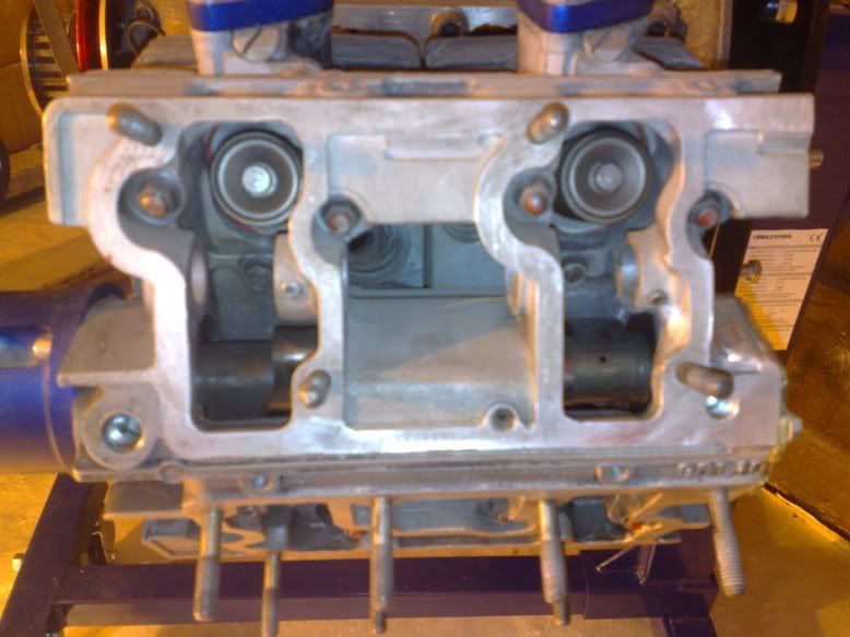
-
Cam

- Posts: 554
- Joined: Tue Jul 25, 2000 12:01 am
Frallan wrote: By the way, I just got the news of a new 911 engine being built.
Pauter block, steel plates and 911 heads.
Currently running 45 psi boost and "only" 610 hp on the dyno. The guys are expecting it to give more than 700 or they feel like losers before even trying it on the strip. I look forward to see this thing.